background image

Fault Mapper Pro Model CA7026 

17


Limited Warranty

The Model CA7026 is warranted to the owner for a period of one year from 

the date of original purchase against defects in manufacture. This limited war

-

ranty is given by AEMC

®

 Instruments, not by the distributor from whom it was 

purchased. This warranty is void if the unit has been tampered with, abused or 

if the defect is related to service not performed by AEMC

®

 Instruments. 

For full and detailed warranty coverage, please read the Warranty 

Coverage Information, which is attached to the Warranty Registration 

Card (if enclosed) or is available at www.aemc.com. Please keep the 

Warranty Coverage Information with your records.
What AEMC

®

 Instruments will do:

If a malfunction occurs within the one-year period, you may return the instrument 

to us for repair, provided we have your warranty registration information on file 

or a proof of purchase. AEMC

®

 Instruments will, at its option, repair or replace 

the faulty material.

REGISTER ONLINE AT:

www.aemc.com

Warranty Repairs

What you must do to return an Instrument for Warranty Repair: 

First,  request  a  Customer  Service Authorization  Number  (CSA#)  by  phone 

or by fax from our Service Department (see address below), then return the 

instrument along with the signed CSA Form. Please write the CSA# on the 

outside of the shipping container. Return the instrument, postage or shipment 

pre-paid to:

Ship To:

  Chauvin Arnoux

®

, Inc. d.b.a. AEMC

®

 Instruments


15 Faraday Drive • Dover, NH 03820 USA


Phone: (800) 945-2362  (Ext. 360)


(603) 749-6434  (Ext. 360)


Fax:  (603) 742-2346 or (603) 749-6309


E-mail: [email protected]

Caution:

 To protect yourself against in-transit loss, we recommend you insure 

your returned material.

NOTE: You must obtain a CSA# before returning any instrument.

Summary of Contents for CA7026

Page 1: ...CA7026 FAULT MAPPER PRO GRAPHICAL TDR FAULT MAPPER PRO TDR GR FICO E N G L I S H User Manual E S PA O L Manual de Instrucciones PORTUGUESE Manual de Usu rio...

Page 2: ...nded calibration interval for this instrument is 12 months and begins on the date of receipt by the customer For recalibration please use our calibration services Refer to our repair and calibration s...

Page 3: ...on 8 4 2 Accuracy and Velocity of Propagation Vp 8 4 3 Getting Started 9 4 4 Set up Mode 9 4 5 Backlight 10 4 6 Tone Generator 10 4 7 Determining and Measuring Vp Values 11 4 8 Adjusting the Vp Value...

Page 4: ...of the operator 1 1 International Electrical Symbols This symbol signifies that the instrument is protected by double or reinforced insulation Use only specified replacement parts when servicing the...

Page 5: ...laim immediately with the carrier and notify your distributor at once giving a detailed description of any damage Save the damaged packing container to substantiate your claim 1 3 Ordering Information...

Page 6: ...stances read off The Fault Mapper Pro has a selectable impedance facility allowing it to be matched to the cable under test This automatically eliminates the trans mission pulse from the display enabl...

Page 7: ...R AEMC Instruments Fault Mapper Pro Vx x Vp 70 Z 100 1 1 BNC input connector 2 Graphical LCD 3 Cable select and Vp Velocity of Propagation decrement button 4 Test function select button 5 Backlight bu...

Page 8: ...n circuit or 1 5V into 50 load 25ns min to 2 15 s dependent on range Cable Impedance Selectable between 50 75 100 Display Resolution 128 x 64 pixel Graphical LCD Display Backlight Electroluminescent T...

Page 9: ...F 20 to 70 C 5 to 95 RH non condensing Operating Temperature 32 to 112 F 0 to 40 C 5 to 95 RH non condensing Altitude 6000 ft 2000m max Dimensions 6 5 x 3 5 x 1 5 165 x 90 x 37mm Weight 12oz 350g Inde...

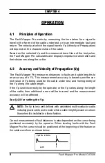
Page 10: ...accuracy of 1 This measurement accuracy is based upon the cor rect value of Vp being used for the cable under test and homogeneity of the Vp along the cable length If the Vp is set incorrectly by the...

Page 11: ...button then press the TEST button to enter set up mode Vp 72 Z 100 Feet Contrast Vp can be set in the range 1 to 99 see 4 8 Z the cable impedance can be set to 50 75 or 100 Measurement units can be se...

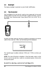
Page 12: ...ble Tracer Model TR03 Cat 2127 76 or equivalent Pressing the TDR button will inject a warbling oscillating tone into the cable or link under test When set the following will be displayed Warble Tone T...

Page 13: ...ecial cable applications This is quite easy 1 Take a cable sample of exact length increments ft or m longer than 60 ft 20m 2 Measure the exact length of the cable using a tape measure 3 Connect one en...

Page 14: ...attachment is via a BNC connector located at the top of the unit For unterminated cables use the alligator clip attachment provided Coaxial Cable Connect the Black clip to the center wire and the Red...

Page 15: ...The vertical cursor line is moved left and right along the line of the trace by pressing the and buttons To determine the distance to an event position the cursor at the beginning of the event and rea...

Page 16: ...t Mode Saves on battery life and also enables the Fault Mapper Pro to be disconnected from the cable while still leaving the fault display on the screen To enter Continuous Scanning mode press and hol...

Page 17: ...screws and remove the battery compartment cover 3 Replace the batteries with 4 x 1 5V AA alkaline batteries observing the polarities 4 Reattach the battery compartment cover 5 2 Cleaning Disconnect t...

Page 18: ...Inc d b a AEMC Instruments 15 Faraday Drive Dover NH 03820 USA Phone 800 945 2362 Ext 360 603 749 6434 Ext 360 Fax 603 742 2346 or 603 749 6309 E mail repair aemc com Or contact your authorized distri...

Page 19: ...y return the instrument to us for repair provided we have your warranty registration information on file or a proof of purchase AEMC Instruments will at its option repair or replace the faulty materia...

Page 20: ...18 Fault Mapper Pro Model CA7026 Notes...

Page 21: ...rincipios de Funcionamiento 26 4 2 Precisi n y Velocidad de Propagaci n Vp 26 4 3 Comenzando 27 4 4 Modo de Configuraci n 27 4 5 Retroiluminaci n 28 4 6 Generado de Tono 28 4 7 Determinando y Midiendo...

Page 22: ...S mbolos El ctricos Internacionales Este s mbolo significa que el instrumento esta protegido por un doble aislamiento o un aislamiento reforzado Utilice piezas de repuesto especificadas por AEMC cuan...

Page 23: ...estar da ada reclame a la empresa que le entrego la mercanc a y llame a su distribuidor d ndole con todo detalle el los da os 1 3 Informaci n del pedido Fault Mapper Pro Modelo CA7026 Cat 2127 81 Incl...

Page 24: ...lar la impedancia del cable que se va a comprobar Esto autom ti camente elimina el pulso de transmisi n desde la pantalla facilitando la identificaci n del fallo La Velocidad de Propagaci n Vp es ajus...

Page 25: ...p 70 Z 100 1 1 Conector de entrada BNC 2 LCD Grafico 3 Bot n de selector de cable y decremento de Vp Velocidad de Pro pagaci n 4 Selector de funci n de prueba Test 5 Bot n para la retroiluminacion 6 B...

Page 26: ...s a 2 15 s dependiendo del rango Resoluci n de Pantalla 128 x 64 p xel LCD Retroiluminacion Electro luminescente Generador de Tono Tono 810Hz 1110Hz Advertencia de Voltaje Triggers a 10V AC DC Velocid...

Page 27: ...tura de Trabajo 32 hasta 115F 0 hasta 40C 5 95 RH sin condensaci n Altitud 6000 ft 2000m max Dimensions 6 5 x 3 5 x 1 5 165 x 90 x 37mm Peso 12oz 350g ndice de Protecci n IP54 Seguridad IEC61010 1 EN6...

Page 28: ...valor correcto de Vp siendo usado por el cable que se esta probando y de la homogenei dad de Vp a lo largo del cable En el caso que Vp se configure incorrectamente por el usuario o que Vp var e a lo...

Page 29: ...4 Modo de Configuraci n Sujetar el bot n TDR despu s presione el bot n TEST para entrar en el modo de configuraci n Vp 72 Z 100 Feet Contrast Vp puede ser configurado en un rango de 1 hasta 99 ver 4...

Page 30: ...uminaci n de la pantalla se enciende y se apaga con el bot n 4 6 Generado de Tono El Fault Mapper Pro tambi n puede ser utilizado como generador de tono para seguir e identificar cables o hilos El usu...

Page 31: ...ces este valor no se puede conseguir o el usuario desear a determinarlo para compensar las variaciones del cable o para una aplica ci n especial del cable Es muy sencillo 1 Tome un cable como muestra...

Page 32: ...r BNC localizado en la parte superior de la unidad Para indeterminados tipos de cable se dispone de unas pinzas de tipo cocodrilo Cable Coaxial Conecte la pinza negra al hilo de en medio y la pinza ro...

Page 33: ...de cursor se puede mover de izquierda a derecha a lo largo del trazado de la se al presionando lo botones and Para determinar la distancia de una prueba posicione el cursor al principio de la prueba y...

Page 34: ...nado En el Modo de Adquisici n Unica Ahorramos bater a y tambi n posibilitamos al Fault Mapper Pro a estar desco nectado del cable cuando aun tenemos el fallo mostrado en pantalla Para seleccionar el...

Page 35: ...illos y quite la cubierta de las bater as 3 Reemplace las bater as con 4 x 1 5V AA bater as alcalinas obser vando la polaridad 4 Coloque de nuevo la cubierta de las bater as y enrosque los tornillos 5...

Page 36: ...envase Env e a Chauvin Arnoux Inc d b a AEMC Instruments 15 Faraday Drive Dover NH 03820 USA Fono 603 749 6434 Ext 360 Fax 603 742 2346 or 603 749 6309 E mail repair aemc com O contacte su distribuido...

Page 37: ...araci n sin costo alguno aseg rese de mandar nos la Tarjeta de Registro Si no disponemos de la tarjeta de registro del instrumento necesitaremos una prueba con fecha de la adquisici n al igual que la...

Page 38: ...36 Fault Mapper Pro Modelo CA7026 Notas...

Page 39: ...a o 44 4 2 Precis o e Velocidade de Propaga o Vp 44 4 3 Iniciando 45 4 4 Modo Configura o 45 4 5 Backlight 46 4 6 Gerador de Tom 47 4 7 Determinando e Medindo Valores da Vp 48 4 8 Ajustando o Valor da...

Page 40: ...e do operador 1 1 S mbolos El tricos Internacionais Este s mbolo indica que o instrumento protegido por isola o dupla ou refor ada Utilize somente pe as autorizadas ou reco mendadas pelo fabricante qu...

Page 41: ...o reclame imediatamente com a transportadora e ao mesmo tempo notifi que o seu distribuidor 1 3 Informa es para Pedido Fault Mapper Pro Modelo CA7026 No de Cat logo Cat 2127 81 Inclui o instrumento bo...

Page 42: ...do gr fico e as dist ncias s o automaticamente atualizadas e exibidas com base na nova posi o do cursor O Modelo CA7026 possui um seletor de imped ncias que permite o casa mento de imped ncias entre...

Page 43: ...x x Vp 70 Z 100 1 1 Conector de entrada tipo BNC 2 LCD gr fico 3 Bot o para sele o do tipo de cabo redu o do valor da Vp Veloci dade de Propaga o 4 Bot o de sele o Teste Fun o 5 Bot o Liga Desliga o B...

Page 44: ...50 Imped ncia do Cabo Selecion vel entre 50 75 e 100 Pulso de Sa da 25ns min a 2 15 s dependendo da faixa Resolu o do Display Display de LCD gr fico de 128 x 64 pixel Backlight do Display Eletrolumine...

Page 45: ...20 a 70 C 4 a 158 F 5 a 95 HR sem condensa o Temperatura de Opera o 0 a 40 C 32 a 112 F 5 a 95 HR sem condensa o Altitude 2 000m 6 000ft m x Dimens es 165 x 90 x 37mm 6 5 x 3 5 x 1 5 Peso 350g 12oz nd...

Page 46: ...s o de 1 Esta precis o nas medi es assume que tenha sido informado ao instrumento o valor correto da Vp correspondente ao cabo sob teste e que a Vp seja homog nea ao longo de todo o comprimento do cab...

Page 47: ...da Velocidade de Propaga o a imped ncia do cabo e o indicador do n vel de carga da bateria AEMC Instruments Fault Mapper Pro V1 0 Vp 70 Z 100 4 4 Modo Configura o Mantenha pressionado o bot o TDR e pr...

Page 48: ...o bot o TDR novamente para salvar as mudan as e sair do Modo Configura o Quando o Fault Mapper Pro Modelo CA7026 desligado ele armazenar na sua mem ria interna os par metros de configura o atuais Est...

Page 49: ...R03 Cat 2127 76 ou equivalente Pressionando o bot o TDR ir injetar um tom oscilat rio atrav s do cabo ou link sob teste Quando estiver ajustado a seguinte tela ser exi bida Warble Tone O sinal injetad...

Page 50: ...conseguido 1 Pegue uma amostra do cabo com comprimento exato em metros ou p s por m maior que 20m 60ft 2 Me a o comprimento exato do cabo usando uma fita m trica 3 Conecte uma das extremidades do cab...

Page 51: ...ta por meio de um conector tipo BNC localizado na parte superior do instrumento Para cabos sem termina es utilize o adaptador com garras tipo jacar fornecido junto com o equipamento Cabo Coaxial Conec...

Page 52: ...a de teste Vp 72 Z 100 413ft O tela representada a seguir exibe o gr fico equivalente ao de um cabo com irregularidades de imped ncia Vp 72 Z 100 210ft Pressionando se o bot o and a linha vertical do...

Page 53: ...este modo o Fault Mapper Pro envia um pulso nico ao longo do cabo sob teste quando qualquer um dos bot es ou ou TEST for pressio nado Modo de Varredura Simples Economiza a carga da bat eria e permite...

Page 54: ...rumento 2 Desaperte os 2 parafusos e remova a tampa do compartimento da bateria 3 Substitua as baterias por 4 baterias alcalinas tipo AA de 1 5V obser vando as polaridades 4 Reposicione e aparafuse no...

Page 55: ...a embalagem na qual o instrumento ser en viado Chauvin Arnoux Inc d b a AEMC Instruments 15 Faraday Drive Dover NH 03820 USA Tel 603 749 6434 Ext 360 Fax 603 742 2346 or 603 749 6309 repair aemc com O...

Page 56: ...os em nossos arquivos o seu CART O DE RE GISTRO A AEMC ir conforme a sua conveni ncia consertar o item com falha Se o cart o de registro n o estiver em nossos arquivos n s iremos solicitar uma prova d...

Page 57: ...Fault Mapper Pro Modelo CA7026 55 Notas...

Page 58: ...11 11 99 MAN 100270 v12 Chauvin Arnoux Inc d b a AEMC Instruments 15 Faraday Drive Dover NH 03820 USA Phone 603 749 6434 Fax 603 742 2346 www aemc com...

Reviews: