background image

SETUP GUIDE

This product is legal in California for racing vehicles only and should never be used on public

highways.  AEM Performance Electronics, 2205 W. 126th Street Unit A, Hawthorne, CA 90250,

Phone: (310) 484-2322 Fax: (310) 484-0152

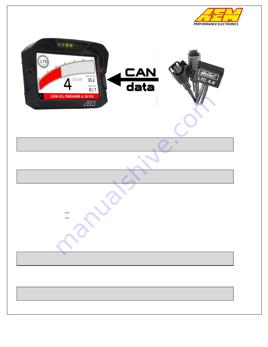
MoTeC LTC to CD Dash

Supported Devices

MoTeC LTC / LTCD / LTC NGK / LTCD NGK

CAN Bus Wiring

AEM CD has 2 separate CAN ports. For 3rd party devices, AEM recommends you use AEM CAN Bus 2, whose
connections are contained in a 2 pin Deutsch DTM connector. On older harnesses it may be in an unterminated,
twisted/shielded flying lead in the dash harness.

MoTeC LTC (CAN HIGH) 

  AEM CD "CAN 2" Pin 1 (CAN 2+), Gray wire in twisted/shielded pair

MoTeC LTC (CAN LOW)


 AEM CD "CAN 2" Pin 2 (CAN 2-), Black wire in twisted/shielded pair

The AEM CD Dash has a software selectable CAN termination resistor. Each network needs 2 terminating
resistors, one at each end. The LTC wideband does not have an internal terminating resistor and relies on external
Terminating plugs. You can either use those or replace one of them with the internal CD Dash resistor. You must
have 2 in total, one at each end of the network.

MoTeC LTC Software Setup

The MoTeC LTC Manager software is not required if using a single LTC or LTCD unit pre-configured by MoTeC. 
The DBC file provided for the LTC/LTCD by AEM matches this default configuration.

Supported Channels

The AEM CD Dash supports 16 unique channels transmitted from the MoTeC LTC and 32 from the LTCD.

Summary of Contents for MoTeC LTC to CD Dash

Page 1: ... Gray wire in twisted shielded pair MoTeC LTC CAN LOW AEM CD CAN 2 Pin 2 CAN 2 Black wire in twisted shielded pair The AEM CD Dash has a software selectable CAN termination resistor Each network needs 2 terminating resistors one at each end The LTC wideband does not have an internal terminating resistor and relies on external Terminating plugs You can either use those or replace one of them with t...

Page 2: ...raw 26 LTC2_Ip_raw 11 LTC1_Ipn_raw 27 LTC2_Ipn_raw 12 LTC1_Lambda_raw 28 LTC2_Lambda_raw 13 LTC1_Ri_raw 29 LTC2_Ri_raw 14 LTC1_SensorControlFault_raw 30 LTC2_SensorControlFault_raw 15 LTC1_SensorState_raw 31 LTC2_SensorState_raw 16 LTC1_SensorWireShort_raw 32 LTC2_SensorWireShort_raw AEM Setup in DashDesign AEM has provided some pre configured layouts that can be easily adapted to accept display a...

Page 3: ...racing vehicles only and should never be used on public highways AEM Performance Electronics 2205 W 126th Street Unit A Hawthorne CA 90250 Phone 310 484 2322 Fax 310 484 0152 4 Under the CAN Receive tab click the drop down next to Show and select Port 2 ...

Page 4: ...n California for racing vehicles only and should never be used on public highways AEM Performance Electronics 2205 W 126th Street Unit A Hawthorne CA 90250 Phone 310 484 2322 Fax 310 484 0152 5 Under the CAN Receive tab select Import CAN ...

Page 5: ...ing vehicles only and should never be used on public highways AEM Performance Electronics 2205 W 126th Street Unit A Hawthorne CA 90250 Phone 310 484 2322 Fax 310 484 0152 6 Navigate to the aemcan dbc file for your application Select the file and click Open ...

Page 6: ...and the drop downs and see all of the available CAN channels for your device You may choose to import all of the channels available or you may select only the channels you wish to display Just be sure to include LTC1_Lambda and LTC2_Lambda if applicable as a selected channel For this example we will include all available channels If using a LTCD you will see twice as many channels available here O...

Page 7: ... AEM Performance Electronics 2205 W 126th Street Unit A Hawthorne CA 90250 Phone 310 484 2322 Fax 310 484 0152 8 In the Setup Editor under the CAN Receive tab Port 2 check to make sure the channel names you selected to import are present If they are not go back to step 4 and try again As you can see below all of the ...

Page 8: ...1 and set its Primary Input to LTC1_Lambda or select Insert to create a new channel Name your new channel LTC1_AFR or similar so it is easy to keep track of Set the Primary Input to LTC1_Lambda 10 Now you need to select the correct conversion for your fuel type and preferred display units Select the drop down under the Operation column for AFR1 or your new channel and scroll down to Convert Lambda...

Page 9: ...e to display AFR This should open the Value Editor Dynamic Needle Gauge Editor or Bar Editor window Click on the Input drop down and select the channel AFR1 or the channel you created Click Ok Do this for every location in your layout where you wish to display AFR 12 Save the layout Once the layout has been saved connect the dash to your computer and press Ctrl U or File Upload to Display Once the...

Reviews: