background image

56

Safety warnings

For the User

• The cooker hood is designed to extract unpleasant odours from the kitchen, it will not

extract steam.

• Always cover lighted elements, to prevent excess heat from damaging the appliance.

In the case of oil, gas and coal fired cookers it is essential to avoid open flames.

• Also, when frying, keep the deep frying pan on the cooker top/cooker under careful

control.

• The hot oil in the frying pan might ignite due to overheating.
• The risk of self-ignition increases when the oil being used is dirty.
• It is extremely important to note that overheating can cause a fire.
• Never carry out any flambé cooking under the hood.
• Always disconnect the unit from the power supply before carrying out any

work on the hood, including replacing the light bulb (take the cartridge fuse
out of the fuse holder or switch off the automatic circuit breaker).

• It is very important to clean the hood and replace the filter at the

recommended intervals. Failure to do so could cause grease deposits to
build up, resulting in a fire hazard.

For the Installer

• When used as an extractor unit, the hood must be fitted with a  150mm diameter hose.

Should there already be a pipe of diameter 125 mm that ducts to the outside through
the walls or roof, it is possible to use the 150/125 mm reduction flange provided. In
this case the hood will be slightly noisier.

• When installing the hood, make sure you respect the following minimum

distance from the top edge of the cooking hob/ring surfaces:
electric cookers

600 mm

gas cookers

650 mm

coal and oil cookers

700 mm min.

• The national Standard on fuel-burning systems specifies a maximum depression of

0.04 mbar in such rooms.

• The air outlet must not be connected to chimney flues or combustion gas ducts. The

air outlet must under no circumstances be connected to ventilation ducts for rooms in
which fuel-burning appliances are installed.

• The air outlet installation must comply with the regulations laid down by the relevant

authorities.

• When the unit is used in its extractor version, a sufficiently large ventilation hole must

be provided, with dimensions that are approximately the same as the outlet hole.

• National and regional building regulations impose a number of restrictions on using

hoods and fuel-burning appliances connected to a chimney, such as coal or oil room-

Summary of Contents for CHDI 8610

Page 1: ...ugshaube Afzuigkap Hotte Cooker Hood Cappa aspirante Montage und Gebrauchsanweisung Installatie en gebruiksaanwijzing Notice d utilisation et d installation Operating and Installation Instructions Istruzioni di montaggio ed uso ...

Page 2: ...chnischen Problemen steht Ihnen unser WERKSKUNDENDIENST in Ihrer Nähe jederzeit zur Verfügung Adressen und Telefonnummern findenSieimAbschnitt Kundendienststellen Beachten Sie dazu auch den Abschnitt Service AEGDIRECT INFOSERVICES0180 55545 Entsorgung Verpackungsmaterial entsorgen Alle Verpackungsteile sind recyclebar Folien und Hartschaumteile entsprechend gekennzeichnet Verpackungsmaterialundeve...

Page 3: ...lter 7 LED AnzeigeFettfilter D 7 LED AnzeigeAktivkohlefilter E 7 ZurückstellenderSättigungsanzeige 7 Wartung und Pflege 9 Metallfettfilter 9 ÖffnenderMetallfettfilter 9 Aktivkohlefilter 10 AustauschderGlühlampe 11 Reinigung 11 Sonderzubehör 11 Kundendienst 12 SERVICE 12 Technische Daten 13 Zubehör Montagematerial 13 Elektroanschluß 13 SicherheitshinweisefürdenElektro Installateur 13 Montage 14 ...

Page 4: ...u trennen Schraubsicherungen aus der Fassung herausnehmenbzw Sicherungsautomatenabschalten Esistwichtig dieFilterwechselbzw Reinigungsintervalleeinzuhalten Bei Nichtbeachtung besteht infolge von Fettablagerung Feuergefahr für den Küchenmöbel Monteur Das Abluftrohr muß bei Abluftbetrieb einen Durchmesser von 150 mm haben Falls ein Abluftrohr in Wand oder Dach mit einem Durchmesser von 125 mm schon ...

Page 5: ... wenn Raum und oder Wohnung Raum Luftverbund durch eine geeignete Zuluftöffnung von ca 500 600 cm2 von außen belüftet sind und dadurch bei laufender Dunstabzugshaube Unterdruck vermieden wird ImZweifelsfalleRatundZustimmungdeszuständigenBezirks Schornsteinfegermeisters oder der örtlichen Baubehörde einholen Da in Räumen ohne Feuerungsstätte die Regel gilt Zuluftöffnung so groß wie Abluftöffnung ka...

Page 6: ...trohr in Wand oder Dach mit einen Durchmesser von 125 mm schon besteht kanndermitgelieferte Reduzierstutzen 150 125 mm verwendet werden Das Betriebsgeräusch wird dann etwashöher Zusammenmitdem ReduzierstutzenkannderAblaufschlauch125 montiert werden Sonderzubehör ABS 125 E Nr 942 118 612 Wird der Küchendunst durch die Außenwand ins Freie geleitet wird der Mauerkasten MKZ E Nr 942 118 609 150 mm Ø a...

Page 7: ...e 2 und Sättigungsanzeige Fettfilter LED Blinken der Anzeige E Anzeige Stufe 3 und Sättigungsanzeige Aktivkohlefilter LED Blinken der Anzeige F Anzeige Intensivstufe LED G EinschalterIntensivstufe Nach 5 Minuten schaltet die Intensivstufe in die vorher eingestellteStufezurückbzw schaltetaus wenn keineStufeeingestelltist UmdieIntensivstufevor Ablauf von 5 Minuten zu beenden muß Knopf A oder B gedrü...

Page 8: ...ie Tasten B und G erneut für 3 Sekunden gedrückt halten bis die LED AnzeigeAktivkohlefilterEerlischt LED Anzeige Fettfilter D Die LED Anzeige D blinkt wenn der Fettfilter gereinigt werden muss Dies ist nach ca 40 Betriebsstunden der Fall Die Wartungsvorschriften der Fettfilter sind zu beachten sh auch Seite 10 und 13 LED Anzeige Aktivkohlefilter E Die LED Anzeige E Aktivkohlefilter blinkt wenn der...

Page 9: ...en herausnehmen Bild 3 Handreinigung Metallfettfilterkassetteca 1Stundeinheißem WassermitfettlösendemReinigungsmittel einweichen und danach mit heißem Wasser abbrausen Evtl Vorgang wiederholen AbgetrockneteKassettewiedereinbauen Geschirrspüler MetallfettfilterkassetteinGeschirrspülerstellen ReinigungbeistärkstemReinigungsprogramm und höchster Temperatur mind 65 C Evtl Vorgangwiederholen Abgetrockn...

Page 10: ...setzen und später schlechte Gerüche verursachen können Um die Kohle wieder zu aktivieren muß der Filter im Backofen getrocknet werden Ober und Unterhitze sowie eine Temperatur von maximal 100 C wählen und den Filter 10 Minutenlangtrocknen Nach etwa 3 Jahren muß der Filter ausgetauscht werden da dann seine Dunstaufnahmefähigkeitumca 50 reduziertist Montage Den Rahmen i des Filters h entnehmen dazu ...

Page 11: ...ermontieren Bevor der Kundendienst gerufen wird weil die Glühlampenichtbrennt erstprüfen obsiefest eingestecktist Reinigung Achtung Zum Reinigen der DunstabzugshaubeGerät vomStromnetz trennen NichtmitspitzenGegenständenindasSchutzgitterdesMotorseindringen Die äußeren Teile mit milder Spüllauge reinigen Scharfe Reinigungsmittel Bürste oder Scheuersand vermeiden DieSchalterblendeunddasFettfiltergitt...

Page 12: ...undendienstbesuch nötig ist HaltenSiemöglichstgenaufest Wie äußert sich die Störung Unter welchen Umständen tritt die Störung auf Notieren Sie für das Gespräch unbedingt folgende Kennziffern Ihres GerätesaufdemTypschild E Nr 9 Stellen F Nr 8 Stellen DasTypenschildistnachAusbauderMetallfettfilteraufderInnenseite desGeräteszugänglich Wirempfehlen dieKennzifferhiereinzutragen damitSiesiestetszur Hand...

Page 13: ...schild verzeichneteSpannungderNetzspannungentspricht FallsdasGerätmitStecker ausgerüstetist kannesanjedevorschriftsmäßiginstallierteundgutzugängliche Steckdoseangeschlossenwerden Bei erforderlichem Festanschluß darf die Dunstabzugshaube nur durch einen beim zuständigen Elektrizitäts Versorgungsunternehmen eingetragenen Elektro Installateur angeschlossen werden Installationsseitig ist eine allpolig...

Page 14: ...so in die äußeren Löcher einschrauben daß zwischen Schraubenkopf und Decke ein Abstand von ungefähr 1 cm verbleibt 4 Ein Abluftrohr in das Innere des Gerüstes 5 einführen und mit dem Flansch des Gebläseaustrittsverbinden AbluftrohrundRohrschellennichtimLieferumfang enthalten Das Traggerüst an den vier Deckenschrauben einhängen 6 siehe auch 4 ACHTUNG Die Gerüstseite mit der Anschlußbuchse entsprich...

Page 15: ...15 Bild 6 2a 3 4 4 4 4 4 4 6 6 7 7 7 7 8 8 2a 5 7 9 10 10 10 10 11 11 14 5 273 273 244 214 190 6 12 2b 2b ...

Page 16: ...beiden unteren Kaminsegmente zur Abdeckung des Gerüstes 18 zusammenbauen dazu sechs Schrauben verwenden 3 pro Seite siehe auch Schemazeichnung für den Zusammenbau der beiden Segmente Das untere Segment des Kamins so in den speziellen Sitz einbauen daß es den Motorraum und die Verbindungsdose vollkommen abdeckt und mit zwei Schrauben vom Innern der Dunstabzugshaube befestigen 19 MitzweiProfilen 20 ...

Page 17: ...17 15 15 15 15 15 16 16 15 15 13F F 13A 15 14 Bild 7 ...

Page 18: ...18 19 18 18 18 18 18 18 18 18 18 18 M X 17 17 19 20 X 20 Bild 8 ...

Page 19: ...tsenkrijgtubijdegemeentelijke reinigingsdienstofhetgemeentehuis Waarschuwing Afgedankte apparaten moeten voor het weggooien onbruikbaar worden gemaakt Aansluitsnoer verwijderen eerst de stekker uit het stopcontact trekken resp bij vaste aansluiting de aansluiting door een vakman laten demonteren Geachte klant Leesdezeinformatieaandachtigdoor Lees vooral het hoofdstuk Veiligheid op de eerste pagina...

Page 20: ...ters 25 LED indicatievetfilters D 25 LED indicatiekoolfilter E 25 Verzadigingsindicatieterugzetten 25 Onderhoud 26 Metalenvetfilters 26 Demonterenvandemetalenvetfilters 26 Koolfilter 27 Vervangen van de gloeilamp en 28 Reiniging 28 Extra leverbare accessoires 28 Klantenservice 29 Technische gegevens 32 Toebehoren Montagemateriaal 32 Elektrische aansluiting 32 Veiligheidsaanwijzingenvoordeelektro i...

Page 21: ...eubel monteur De afvoerbuis moet bij gebruik als afzuigkap een diameter van 150 mm hebben Als de keukenluchtjes door de buitenmuur naar buiten worden geleid is een telescoop muurkast extra leverbaar accessoire MKZ E nr 942 118 609 nodig Als een afvoerbuis in wand of dak met een diameter van 125 mm al aanwezig is kan het meegeleverde verloopstuk 150 125 mm worden gebruikt Samen met het verloopstuk ...

Page 22: ... ca 500 600 cm2 van buiten geventileerd zijn waardoor bij lopende afzuigkap een onderdruk vermeden wordt Omdat in ruimten zonder rookkanaalafvoer de regel geldt toevoeropening even groot als afvoeropening kan door de grotere opening van 500 600 cm2 de werking van de afvoerinrichting nadelig beïnvloed worden Het gebruik van het apparaat als recirculatiekap is onder de genoemde omstandigheden zonder...

Page 23: ...moetde afvoerbuis dezelfde diameter hebben als de afvoeropening Als een afvoerbuis in wand of dak met een diameter van 125 mm al aanwezig is kan het meegeleverde verloopstuk 150 125 mm worden gebruikt Het bedrijfsgeluid wordt dan iets hoger Samen met het verloopstuk kan de afvoerslang 125 worden gemonteerd afb 1 A Gebruik als recirculatiekap De lucht wordt door koolfilters gefilterd en weer de keu...

Page 24: ...ndicatie stand 1 LED D indicatie stand 2 en vetfilter verzadigd LED lampje knippert E indicatie stand 3 en koolfilter verzadigd LED lampje knippert F indicatieintensief stand LED G inschakelenintensief stand na 5 minuten intensief stand schakelt de kap op de eerder ingestelde stand terug resp uit als geen stand is ingesteld Om de intensief stand eerder te beëindigen knop A of B indrukken H uitscha...

Page 25: ...e indicatie uit te schakelen toets B en G tegelijk 3 seconden ingedrukt houden tot de LED indicatiekoolfiterEuitgaat LED indicatie vetfilters D De LED indicatie D knippert als de vetfilters moeten worden gereinigd Dat is na ca 40 gebruiksuren het geval Zie hoofdstuk Onderhoud Metalen vetfilters LED indicatie koolfilter E De LED indicatie E knippert als het koolfilter moet worden vervangen Dat is n...

Page 26: ... van de metalen vetfilters eerst naar achteren en trek de cassette dan naar beneden Afb 3 Reinigen met de hand Metaalfiltercassetteca 1uurinheetwatermet eenvetoplossendschoonmaakmiddelweken en daarna met heet water afspoelen Proces evt herhalen Cassette afdrogen en weer inzetten Afwasautomaat Metaalfiltercassetteindeafwasautomaatzetten Sterksteprogrammaenhoogstetemperatuur min 65 C kiezen Proces e...

Page 27: ...stzetten die later nare luchtjes kunnen veroorzaken Om de kool weer te activeren moet het filter in de oven worden gedroogd Boven en onderwarmte en een temperatuur van maximaal 100 C kiezen en het filter 10 minuten lang drogen Na ca 3 jaar moet het filter worden vervangen omdat dan het vermogen om wasem op te nemen minder is geworden Montage Het frame i van het filter h losnemen daartoe schroef g ...

Page 28: ...en gelijkwaardige lamp vervangen Afdekkapjeweermonteren Voordatucontactopneemtmetonzeservice afdeling omdatdegloeilampnietbrandt eerst controleren of de lamp stevig vast zit Reiniging Attentie eerstdestekkeruithetstopcontacttrekken Geen spitse voorwerpen in het beschermrooster van de motor steken De buitenkant van het apparaat met een mild sopje reinigen Gebruik geen scherpe reinigingsmiddelen bor...

Page 29: ...zoek servicetechnicus tel 0172 468 300 fax 0172 468 255 Belangrijk Houd bij het opgeven van een storing altijd het E nr en F nr van uw apparaat bij de hand Deze nummers vindt u op de binnenzijde van de afzuigkap nadat u de vetfilters hebt losgenomen en kunt u het beste hieronder noteren E nr F nr Bereid het gesprek altijd goed voor Zo vergemakkelijkt u de diagnose en de beslissing of bezoek van ee...

Page 30: ...rspronkelijke reparatie door redelijkerwijs niet te voorziene omstandigheden niet tegen het begrote bedrag kan worden uitgevoerd of b ook andere dan in de begroting voorziene reparaties noodzakelijk zijn zal overleg met de consument plaatsvinden en een herziene kostenbegroting worden gemaakt In geval de consument daarmee alsnog niet akkoord gaat geldt eveneens het in artikel 2b bepaalde Art 4 De r...

Page 31: ...niet verwacht kan worden zal aan de consument een nieuw exemplaar of soortgelijk toestel van hetzelfde merk worden aangeboden tegen bijbetaling op basis van een per product te bepalen jaarlijks afschrijvingspercentage Art 8 Vervangen onderdelen stelt de technicus weer ter beschikking van de consument met uitzondering van de onder garantie of tegen een gereduceerde prijs vervangen onderdelen Art 9 ...

Page 32: ...ing op het typeplaatje overeenkomt met de netspanning Als het apparaat is voorzien van een stekker kan het aan elk volgens de voorschriften geïnstalleerd en goed bereikbaar stopcontact worden aangesloten Als vaste aansluiting noodzakelijk is mag het apparaat alleen door een erkend elektro installateurwordenaangesloten Indeelektrischeinstallatiemoeteeninrichtingzijn aangebrachtdiehetmogelijkmaaktom...

Page 33: ...geleverde sleutel enlaateenruimtevanongeveer1cmtussendekopvandeschroefenhet plafond over 4 Plaatsdebijgeleverdeafvoerbuisinhetframe 5 ensluithemaanopdekoppelingsring vandemotorruimte afvoerbuisenbevestigingsbandjeswordennietbijgeleverd Haak het frame op de 4 schroeven 6 zie handeling 4 LETOP Dezijdevanhetframemetdeaansluitdooskomtovereenmetdezijdevanhet bedieningspaneelwanneerdekapgemonteerdis Dra...

Page 34: ...34 afb 6 2a 3 4 4 4 4 4 4 6 6 7 7 7 7 8 8 2a 5 7 9 10 10 10 10 11 11 14 5 273 273 244 214 190 6 12 2b 2b ...

Page 35: ...twee bovenste delen 18 van de schouw voor afdekking van het frame aan elkaar gebruik 6 schroeven 3 aan elke zijde zie ook het schema voor koppeling van de twee delen Breng het onderste deel van de schouw op zijn plaats aan zodat de motorruimte en de aansluitdoos volledig bedekt zijn en zet het met twee schroeven vast vanuit de binnenkant van de wasemkap 19 Breng de 2 strips 20 bijgeleverd op de be...

Page 36: ...36 15 15 15 15 15 16 16 15 15 13F F 13A 15 14 afb 7 ...

Page 37: ...37 19 18 18 18 18 18 18 18 18 18 18 M X 17 17 19 20 X 20 afb 8 ...

Page 38: ...assagedesdéchets déchetteries Consignes de mise au rebut L appareil ne doit pas être jeté avec les ordures ménagères Renseignez vous auprès des services de votre commune des endroits autorisés pour la mise au rebut de l appareil Attention Rendez inutilisable l appareil usagé avant de le mettre au rebut Coupez le câble d alimentation au ras de l appareil Chère cliente cher client Veuillezlireattent...

Page 39: ...44 Lampe témoin de saturation du filtre à graisse D 44 Lampe témoin de saturation du filtre à charbon E 44 Rétablissement du signal de saturation du filtre à graisse et du filtre à charbon 44 Entretien 45 Filtreàgraissemétallique 45 Ouverture du filtre à graisse métallique 45 Filtre à charbon 46 Remplacementdel ampouled éclairage 47 Nettoyage 47 Accessoires en option 47 Service Après vente 48 Cara...

Page 40: ...isé par des adultes Veillez à ce que les enfants n ytouchentpasetnel utilisentpascommeunjouet Votre appareil est destiné à l usage domestique normal Ne l utilisez pas à des fins commerciales ou industrielles ou pour d autres buts que celui pour lequel il a été conçu Ne modifiez pas ou n essayez pas de modifier les caractéristiques de cet appareil Cela représenterait un danger pour vous Débranchez ...

Page 41: ... de la taille de l ouverture d évacuation Selonlesprescriptionsdeconstructionlocales desrestrictionssontimposéesà l utilisationsimultanéedansunemêmepiècedehottesaspirantesetdesystèmesde chauffage reliés à une cheminée tels que des poêles à charbon à mazout ou à gaz Le fonctionnement simultané et sans danger d appareils reliés à une cheminée et de hottesaspirantesn estassuréquesilelocalet oul appar...

Page 42: ...it avoir un diamètre équivalent à celui de l ouverture d évacuation Dans le cas où il existe déjà un tuyau d extraction de l air d un diamètre de 125 mm dans le mur ou sur le toit on pourra utiliser le manchon de réduction 150 125 mm Le bruit de fonctionnement sera un peu plus élevé Fig 1 A Version recyclage L air est filtré par un filtre à charbon et renvoyé dans la cuisine par la grille supérieu...

Page 43: ...sse 1 Led D Lampe témoin vitesse 2 Led et saturation filtreà graisse signal clignotant E Lampe témoin vitesse 3 Led et saturation filtre à charbon signal clignotant F Vitesseintensive Led G Interrupteur de vitesse intensive Envitesseintensive lahottefonctionnependant5minutes Ensuite elle retourne à la vitesse réglée précédemment ou s arrête lorsqu aucune vitesse n est réglée Pour arrêter la hotte ...

Page 44: ...N SATURATION FILTRE À CHARBON E arrêtera de clignoter Lampe témoin de saturation du filtre à graisse D Cevoyantlumineuxclignotepouravertirl usagerquelesfiltresàgraisseontbesoind être lavés Ceciseproduitaprès40heuresd utilisation Lisezattentivementlesconseilsdenettoyageetd entretiendesfiltresàgraisse Lampe témoin de saturation du filtre à charbon E Cevoyantlumineuxclignotepouravertirl usagerquelefi...

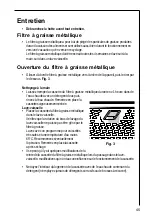
Page 45: ...v 1 heure dans de l eau chaude avec un détergent doux puis rincez à l eau chaude Remettez en place la cassettesoigneusementséchée Lave vaisselle Placezlacassettedufiltreàgraissemétallique dans le lave vaisselle Vérifiez que la rotation du bras de lavage du lave vaisselle ne puisse pas être gêné par le filtreàgraisse Lavez avec un programme pour vaisselles trèssalesetunetempératured aumoins 65 C Re...

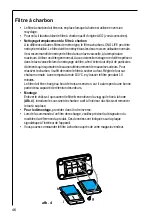
Page 46: ...t de causer ultérieurement de mauvaises odeurs Pour réactiver le charbon il suffit de mettre le filtre à sécher au four Régler le four sur chaleur normale à une température de 100 C et y laisser le filtre pendant 10 minutes Le filtre doit être changé au bout de trois ans environ car il a alors perdu une bonne partie de sa capacité de rétention des odeurs Montage Enlever le châssis i qui soutient l...

Page 47: ...del ampoule Si l ampoule ne s allume pas vérifiez qu elle estcorrectementinstalléeavantd appelerle Service Après Vente Nettoyage Attention Débranchez l appareil avant le nettoyage N introduisezpasd objetspointusdanslagrille deprotectiondumoteur Nettoyez les parties extérieures avec un détergent doux N utilisezjamaisdeproduitsabrasifsoucaustiques dedétergentscorrosifs de brosses ou de sablons à réc...

Page 48: ... visible après ouverture de la grille du filtre à graisse Sous réserve de modifications de construction et de coloris dans le cadre du développementtechnique Caractéristiques techniques Dimensions en cm Hauteur x Largeur x Profondeur 80 106 5 x 100 x 65 Puissance nominale totale 250 W Puissancemoteur 1 x 170 W Eclairage 4 x20 W Longueur du câble d alimentation 150 cm Branchement électrique 220 240...

Page 49: ...es autres appareils branchés Calibre des fusibles en ligne un par phase 10 A en 230 V Important L installation doit être réalisée conformément aux règles de l art aux prescriptions de la norme NF C 15 100 et aux prescriptions de l E D F Utilisez un socle de prise de courant comportant une borne de mise à la terre qui doit être obligatoirement raccordée conformément à la norme NF C 15 100 et aux pr...

Page 50: ...Introduisez le tuyau d évacuation 5 à l intérieur de la structure et raccordez le à la bague de raccord du logement moteur tuyau d évacuation et colliers de fixation non fournis Accrochez la structure aux 4 vis voir opération 6 et 4 ATTENTION Le côté de la structure avec la boîte de connexion correspond au côté du bandeau de commande une fois que la hotte est montée Serrez à fond les 4 vis 7 Intro...

Page 51: ...51 Fig 6 2a 3 4 4 4 4 4 4 6 6 7 7 7 7 8 8 2a 5 7 9 10 10 10 10 11 11 14 5 273 273 244 214 190 6 12 2b 2b ...

Page 52: ...utilisez 6 vis 3 de chaque côté voir aussi schéma en plan pour l assemblage des deux parties Introduisez la partie inférieure de la cheminée dans le logement prévu à cet effet de sorte qu elle recouvre complètementlelogementmoteuretlaboîtedesconnexionsélectriques fixezàl aide de deux vis depuis l intérieur de la hotte 19 Appliquez 2 bordures 20 fournies afin de recouvrir les points de fixation des...

Page 53: ...53 15 15 15 15 15 16 16 15 15 13F F 13A 15 14 Fig 7 ...

Page 54: ...54 19 18 18 18 18 18 18 18 18 18 18 M X 17 17 19 20 X 20 Fig 8 ...

Page 55: ...harcoal filters 60 Grease filter LED D 60 Charcoal filter LED E 60 Resettingthesaturationindicator 60 Maintenance and care 61 Cleaning the hood 61 Metalgreasefilter 61 Removingthemetalgreasefilter 61 Charcoalfilter 62 Changing the light bulb 63 What to do if 64 Special accessories 65 Technical assistance service 65 Technical Specifications 66 Mountingaccessoriesincluded 66 Electrical connection 67...

Page 56: ...ller When used as an extractor unit the hood must be fitted with a 150mm diameter hose Should there already be a pipe of diameter 125 mm that ducts to the outside through the walls or roof it is possible to use the 150 125 mm reduction flange provided In this case the hood will be slightly noisier When installing the hood make sure you respect the following minimum distance from the top edge of th...

Page 57: ...on hole a hole of 500 600 cm2 which is to say a larger hole could reduce the performance of the extractor hood If the hood is used in its filtering function it will operate simply and safely in the above conditionswithouttheneedforanyoftheaforementionedmeasures When the hood is used in its extractor function the following rules must be followed to obtainoptimaloperation short and straight outlet h...

Page 58: ...uld have a diameter equal to the outlet hole For the extractor version this pipe must have a diameterof150mm Should there already be a pipe of diameter 125mmthatductstotheoutsidethroughthe walls or roof it is possible to use the 150 125 mm reduction flange provided In this case the hood will be slightly noisier Fig 1 A Recirculation Version The air is filtered through an activated charcoal filter ...

Page 59: ... reverts to previous speed after 5 minutes If the hood is off when the Intensive speed is activated the hood will be turned off after5minutes To interrupt the Intensive speed press button A or B H Light OFF I LightON Should the hood or the controls fail to operate disconnect the power supply for at least 5 seconds then turn the hood back on again Correct ventilation If the cooker hood is to work c...

Page 60: ...tor will be enabled To disable it Press buttons B and G again simultaneously and hold them for 3 seconds until the charcoal filter LED goes out Grease filter LED D LED D will start to flash when it is time to clean the grease filter Cleaning will be necessary after 40 working hours Always comply with the maintenance instructionsforthegreasefilter Charcoal filter LED E The charcoal filter LED E wil...

Page 61: ...he grease filters is to absorb grease particles which form during cooking and it must always be used either in the external extraction or internal recycling function Attention themetalgreasefiltersmustbe removed and washed either by hand or in the dishwasher every four weeks Removing the metal grease filter First pushthemetalgreasefilterstop backwards then extract the filter pulling downwards Fig ...

Page 62: ...way to clean the filter is in the dishwasher Use normal detergent and choose the highest temperature 65º C Washthefilterseparatelysothatnofoodpartsgetsstuckonthefilterandlatercauses bad odours To reactivate the carbon the filter should be dried in an oven for 10 minuteswithatemperatureofmaximum100ºC After approximately three years of use the carbon filter should be replaced with a new as the odour...

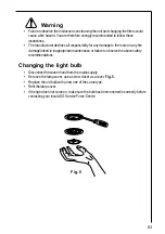
Page 63: ...otor or any fire damage linked to inappropriate maintenance or failure to observe the above safety recommendations Changing the light bulb Disconnect the cooker hood from the mains supply Remove the lamp cover use a screw driver as a lever Fig 5 Replace the old bulb with a new one of the same type Refitthelampcover If the light does not come on make sure the bulb has been inserted in correctly bef...

Page 64: ...ckthat theducting and outlets are not blocked The cooker hood has The safety cut out device has been tripped switched off during operation Turn off the hob and then wait for the device toreset If the hood has been installed below the heightsindicatedintheinstallation instructionsthemotorwillcut outfrequently which will damage the hood If after all these checks the problem persists contact your loc...

Page 65: ...automatically routed to the Service Centre covering your post code area For the address of your local Service Force Centre and further information about Service Force please visit the website at www serviceforce co uk Please ensure that you have read the section What to do if as the engineer will make a charge if the fault is not a mechanical or electrical breakdown even the appliance is under war...

Page 66: ... 65 Maximum absorbed power 250W Motor absorption 1 x 170 W Lighting 4 x20 W Lengthofthecable 150cm Mounting accessories included 1 Reduction flange Ø 150 125 1Deflector 6 Wood screws 6 x 70 mm 6WallplugsØ10mm 10Nuts 8 Metal screw 3 x 9 mm 14 Metal screw 4 x 8 mm 10 Metal screw 4 x 7 mm ...

Page 67: ...y be carried out by an authorised electrician Electrical connection for UK only Safety warnings for the electrician The electric outlet should be placed on the wall inside the chimney The hood has a power cable 150 cm with earth connection and the rated voltage is 220 240 V Connect the hood to the mains supply via a double pole switch whichhas3mmminimumseparationbetweenthecontacts Theswitchmustbea...

Page 68: ...ording FRONT corresponds to the control panel side Prepare the electrical connection Drill as shown 6 holes for 6 wall plugs 4 plugs for fixture screw the outer screws leaving a space of about 1 cm between the screw head and the ceiling 4 Fit an exhaust pipe inside the support 5 and connect it to the motor compartment connection ring exhaust pipe and fixing brackets are not supplied Hook the frame...

Page 69: ...69 2a 3 4 4 4 4 4 4 6 6 7 7 7 7 8 8 2a 5 7 9 10 10 10 10 11 11 14 5 273 273 244 214 190 6 12 2b 2b Fig 6 ...

Page 70: ...ing the two sections Fix the top flue assembly to the support near the ceiling with two screws 16 one each side Carry out electrical connection of control panel and bulbs 17 Join the two bottom sections of the flue covering the support 18 using 6 screws 3 each side see the plan diagram for joining the two sections Insertthebottomsectionoftheflueinitsseatsothatitcompletelycoversthemotor compartment...

Page 71: ...71 15 15 15 15 15 16 16 15 15 13F F 13A 15 14 Fig 7 ...

Page 72: ...72 19 18 18 18 18 18 18 18 18 18 18 M X 17 17 19 20 X 20 Fig 8 ...

Page 73: ...ro grassi D 78 Led indicatore del filtro al carbone attivo E 78 Ripristinodell indicatoredisaturazione 78 Manutenzione e cura 79 Filtrograssiinmetallo 79 Aperturadelfiltrograssiinmetallo 79 Filtro al carbone 80 Sostituzionedellelampade 81 Pulizia 81 Accessori speciali 81 Servizio assistenza tecnica 81 Dettagli tecnici 82 Accessoridimontaggioinclusi 82 Collegamento Elettrico 82 Installazione 83 Uti...

Page 74: ...i grasso comportandorischidiincendio per l installatore Se usata nella versione aspirante la cappa deve essere installata ad un tubo di 150 mmdidiametro Durante l installazione della cappa assicurarsi di rispettare le seguenti distanze minime dai piani di cottura fornelli a gas fornelli elettrici 600mm fornelli a gas 650mm fornelli a carbone e petrolio 700 mm min Lenormenazionalisuisistemi acombus...

Page 75: ...toratoedilizio Poiché nei locali con apparecchi a combustione la norma prevede un foro di uscita delle stesse dimensioni del foro di ventilazione un foro più grande di 500 600 cm2 potrebbe ridurre il rendimento della cappa aspirante Nella versione filtrante la cappa funzionerà senza correre alcun rischio e dover ricorrere alle misure summenzionate Qualora la cappa venisse utilizzata nella versione...

Page 76: ...forodiuscita Per la versione aspirante il tubo deve avere un diametro di 150 mm Se già ci fosse un tubo di 125 mmdidiametrocheconduceall esternoattraversoi muri o il tetto è possibile per utilizzare la flangia di riduzione di 150 125 mm fornita In questo casola cappa sarà leggermente più rumorosa Fig 1 A Versione filtrante L aria passa attraverso il filtro al carbone attivo e viene rimessa nell am...

Page 77: ...filtrograssi spialampeggiante E Indicalavelocità3 LED elasaturazionedelfiltroalcarboneattivo spia lampeggiante F Indicalamassimavelocità LED G Massima velocità accesa spenta LED La massima velocità funziona per cinque minuti Selacappaèaccesaquandovienemessainfunzionelamassimavelocità l apparecchio ritorneràallavelocitàprecedentealterminedeicinqueminuti Selacappaèspentaquandovienemessainfunzionelam...

Page 78: ...o D verrà messo in funzione a questo punto il controllo dello stato di saturazioneèstatoattivato Per spegnere tenere premuti i tasti B e G per tre secondi finché non inizia a lampeggiare il LED spia del filtro al carbone attivo Led indicatore del filtro grassi D Il LED indicatore del filtro grassi C lampeggia quando necessita di essere pulito Seguire le istruzioni per la manutenzione Led indicator...

Page 79: ...tro quindi estrarre il filtro tirando verso il basso Fig 3 Lavaggio dei filtri a mano Lasciare i filtri a bagno per circa un ora in acqua calda con un detersivo sciogli grasso risciacquare abbondantemente con acqua calda Se necessario ripetere l opera zione Rimettere a posto i filtri quando sono asciutti Lavaggio in lavastoviglie Sistemareifiltrinellalavastoviglie Selezionare il programma di lavag...

Page 80: ...di cibo rimanga attaccato al filtro e possa in seguito causare cattivi odori Per poter nuovamente usare il carbone asciugare il filtro nel forno per 10 minuti ad una temperatura massima di 100 C Si suggerisce di sostituire il filtro al carbone dopo circa tre anni in quanto la capacità di assorbimento degli odori potrebbe diminuire Montaggio Togliere la struttura i che sostiene il filtro h svitando...

Page 81: ...motore Per lavare esternamente la cappa usare una soluzione detergente delicata Non utilizzare detergenti caustici polveri o spazzole abrasive Pulire saltuariamente il pannello dei comandi e la griglia del filtro con un panno umido edetergentidelicati E estremamente importante pulire la cappa e sostituire i filtri agli intervalli consigliati L inosservanza delle suddette disposizioni potrebbe caus...

Page 82: ...chelatensionediretecorrisponda allatensioneriportatasull etichettacaratteristiche Gliapparecchifornitidispinapossono esserecollegatiadunapresastandardfacilmenteaccessibile Nel caso in cui fosse necessario un allacciamento fisso la cappa deve essere esclusiva menteinstallatadaunelettricistaiscrittoall albo L installazione deve prevedere un sezionatore omnipolare con distanza minima fra i contattidi...

Page 83: ... con la scriita FRONT corrisponde al lato pannello di controllo Predisporre il collegamento elettrico Forare come indicato 6 fori per 6 tasselli a muro 4 tasselli per l aggancio avvitare 4 viti sui fori esterni lasciando uno spazio tra la testa della vite e il soffitto di circa 1cm 4 Introdurre un tubo di scarico all interno del traliccio 5 e collegarlo all anello di raccordo del vano motore tubo ...

Page 84: ...84 2a 3 4 4 4 4 4 4 6 6 7 7 7 7 8 8 2a 5 7 9 10 10 10 10 11 11 14 5 273 273 244 214 190 6 12 2b 2b Fig 6 ...

Page 85: ...ol assiemecaminosuperiore inprossimitadelsoffitto condueviti 16 una per lato Eseguireilcollegamentoelettricodelcruscottocomandiedellelampade 17 Accoppiare le due sezioni inferiori del camino a copertura del traliccio 18 utilizzare 6 viti 3 per lato vedi anche lo schema in pianta per l accoppiamento delle due sezioni Inserire la sezione inferiore del camino nella apposita sede a copertura completa ...

Page 86: ...86 15 15 15 15 15 16 16 15 15 13F F 13A 15 14 Fig 7 ...

Page 87: ...87 19 18 18 18 18 18 18 18 18 18 18 M X 17 17 19 20 X 20 Fig 8 ...

Page 88: ...LI1R5F Ed 01 03 AEG Hausgeräte GmbH Postfach 1036 D 90327 Nürnberg http www aeg hausgeraete de http www aeg co uk Copyright by AEG ...

Reviews: