background image

7

INPUT & OUTPUT CONNECTIONS

Input Connection 

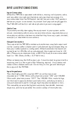
When the TRP500 is operated with ribbon, moving-coil dynamic, tube, 
and any other microphone that does not use phantom power, it is 
recommended that the P48 switch (ref. #4) be set to the OUT position 
before any input is connected, to prevent loud pops when plugged in. 
The P48 LED will be lit in red when phantom power is engaged. 

Cable Care

To prevent possibly damaging the equipment in your system and to 
ensure consistent performance, we recommend you regularly test your 
microphone cables to determine whether they have any open, shorted, 
reversed, or intermittent connections. 

Output Connection 

The output of the TRP500 emulates a transformer-coupled output and 
can be used as either a balanced or unbalanced signal (depending on 
how your cable/system is configured). When balanced, the maximum 
output level is +28 dBu; when unbalanced, the maximum level is +22 
dBu. (These are as measured into a 600 Ohm load; the recommended 
load is > 10K Ohms; 0 dBu = 0.7746 V rms.) 

When unbalancing the XLR output, pin-3 must be tied to ground at the 
receiving end (i.e. the input of the following device).  Use a balanced 
cable to the unbalanced load.  Do not tie pin-3 to ground directly at 
the output of the TRP500. 

Input Impedance 

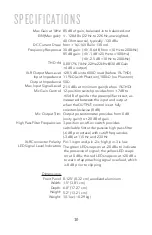
The ultra-high gain DC-coupled JFET circuit has two input 
impedances: 11,900 Ohms with phantom power "ON" and 100,000 
Ohms with phantom power "OFF." The 100,000 Ohm mode brings 
out the best in passive ribbons and tube mics, and also provides a 
unique balanced input for vintage, high-impedance dynamic mics. 
This versatility ensures the highest sensitivity, bandwidth, transient 
response, and clarity possible for a wide variety of microphones.

Summary of Contents for 500 Series

Page 1: ...500 SERIES MICROPHONE PREAMPLIFIER AEA TRP500 OWNER S MANUAL ...

Page 2: ...ch and musical tonality It offers up to 85dB of effortless gain for any microphone and sonics that invite hearts to listen deeper Your TRP500 is 100 percent handcrafted in Pasadena California AEA is a family owned company with a small crew of skilled technicians many of whom are musicians themselves Proudly independent we still manufacture all our ribbon microphones and preamps by hand in house fr...

Page 3: ...CONTENTS WELCOME INTRODUCTION SUPPORT GENERAL GUIDELINES FRONT PANEL GUIDE INPUT OUTPUT CONNECTIONS SETTING THE GAIN SPECIFICATIONS 2 4 4 5 5 7 3 8 10 ...

Page 4: ...s little as possible between you and your audience WARRANTY SUPPORT Your TRP500 comes with a one year limited warranty on parts and labor shipping not included Registering your product with AEA will extend the warranty to a full three years Scan the QR code to register If you should encounter any problems with your TRP500 preamp or have questions regarding specific applications please contact our ...

Page 5: ... to electromagnetic fields or hot surfaces Electromagnetic fields created by power transformers motors or RF transmitters can potentially damage or interfere with the preamp functionality 3 Before turning on the power all connections to the preamp should be made and the Mic Gain and Output Level control set at their minimum setting Be sure to examine the signal chain before powering up the preamp ...

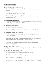
Page 6: ...LED near the switch indicates inverted polarity Phantom Power P48 Switch OUT is off and increases the preamp s input impedance to 100 000 Ohms IN ramps up full spec P48 phantom power to the input which reduces the input impedance to 11 900 Ohms The red LED near the switch indicates when P48 phantom power is engaged Mic Gain Rotary Switch 12 position precision switch adjusts gain from 7 dB to 65 dB...

Page 7: ...r unbalanced signal depending on how your cable system is configured When balanced the maximum output level is 28 dBu when unbalanced the maximum level is 22 dBu These are as measured into a 600 Ohm load the recommended load is 10K Ohms 0 dBu 0 7746 V rms When unbalancing the XLR output pin 3 must be tied to ground at the receiving end i e the input of the following device Use a balanced cable to ...

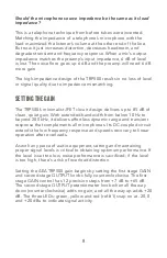
Page 8: ...t gain With extended bandwidth from below 10 Hz to beyond 200 kHz it delivers effortless dynamic range and transient response that complements all microphones Its DC coupled circuit extends the low frequency response and speeds recovery to linear operation after overloads As with any piece of audio equipment setting and maintaining proper signal levels is critical to obtaining optimum performance ...

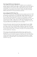
Page 9: ... session Approximate OUTPUT gain at 9 12 and 3 o clock are 3 dB 7 dB and 17 dB The red LED lights 8 dB before clipping with a balanced load so listen carefully to see how it sounds when the red LED lights up more often During rehearsal check the input level adjustment for your DAW console or audio recording device If the red LED is illuminated too often or too long reduce the Mic GAIN one step at ...

Page 10: ... load before 1 THD 11 9kΩ with Phantom 100kΩ no Phantom 50Ω 21 5 dBu at minimum gain before 1 THD 12 position switch provides from 7dB to 65dB of gain for the preamplifier circuit as measured between the input and output when the OUTPUT control is set fully counterclockwise 0 dB Output potentiometer provides from 0 dB unity gain to 20 dB of gain 3 position on off on switch provides switchable firs...

Page 11: ...11 ...

Page 12: ...AEARIBBONMICS COM RIBBONMICS INFO RIBBONMICS COM 800 798 9127 ...

Reviews: