background image

- 3 -

www.advateklights.com

PixLite R2F-S User Manual V200702

2 - Introduction

This is the user manual for the PixLite R2F-S pixel receiver, hardware version 1.0.

The PixLite R2F-S is designed to receive differential long distance signals of 300m
(1000') or more over a standard network cable from a PixLite T8 transmitter unit, and
convert these input signals back into a pixel-ready signal for output directly to pixels.
The PixLite R2F-S features 2 pixel outputs, each having both a dedicated fuse and
'fuse good' LED indicator.

The PixLite R2F-S features a sleek, compact design and 4 holes for ease of wall
mounting as well as an optional DIN rail mounting kit. It also features industrial grade
protection on all inputs and outputs, making it the ideal option for reliable
commercial and industrial applications.

This manual covers physical aspects of the PixLite R2F-S receiver and its essential
setup steps only. Separate user manuals are available for the transmitter units. Other
manuals may be downloaded from here:

www.advateklights.com/downloads

Summary of Contents for PixLite R2F-S

Page 1: ... 1 www advateklights com PixLite R2F S User Manual V200702 PixLite R2F S User Manual Hardware Rev 1 0 ...

Page 2: ...4 3 2 Output Fuses Power Injection 4 3 3 Data Input 5 3 4 Connecting Pixel LEDs 7 4 Operation 9 4 1 Start up 9 4 2 Indicator LEDs 9 4 3 Outputs 10 5 Specifications 11 5 1 Operating Specifications 11 5 2 Mechanical Specifications 11 5 3 Fault Protection 12 6 Troubleshooting 14 6 1 No Power LED 14 6 2 No Pixel Control 14 6 3 Other Issues 14 7 Disclaimer 15 ...

Page 3: ...xLite R2F S features 2 pixel outputs each having both a dedicated fuse and fuse good LED indicator The PixLite R2F S features a sleek compact design and 4 holes for ease of wall mounting as well as an optional DIN rail mounting kit It also features industrial grade protection on all inputs and outputs making it the ideal option for reliable commercial and industrial applications This manual covers...

Page 4: ...A fuses by default You may use any value of fuse up to and including 7 5A depending on your specific application Individual outputs should not exceed 7 5A and the total current should not exceed 15A If your application requires more current than this then you will need to inject power into the pixels directly The number of pixels that can be physically powered through this device may not be as hig...

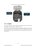
Page 5: ... suitable replacement fuse is of type F7 5A E 32V An additional spare fuse is also provided for quick replacement which can be accessed by opening the lid as shown in Figure 2 below Figure 2 Internal View of the PixLite R2F S 3 3 Data Input Data is connected via a standard network cable into the RJ45 jack located on the front panel of the unit as shown in Figure 3 below Figure 3 Position of Data I...

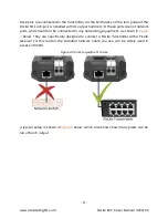
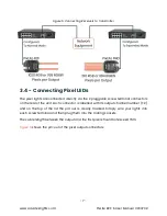
Page 6: ... are not network ports and should not be connected to any networking equipment as shown in Figure 4 below They are specifically designed to connect a PixLite transmitter with a PixLite receiver For this reason the standard network cable you use can be safely used in excess of 300m Figure 4 Correct equipment to use A typical setup is shown in Figure 5 below which also shows how many pixels can be r...

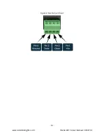
Page 7: ...rew terminal connectors on the rear of the unit Each connector is labelled with its output channel number 1 2 and on the top of the lid the pin out is clearly marked Simply wire your lights into each screw terminal and then plug them into the mating sockets The cable length between the output and the first pixel should not exceed 15m Figure 6 shows the pin out of the pixel output connectors ...

Page 8: ... 8 www advateklights com PixLite R2F S User Manual V200702 Figure 6 Pixel Output Pinout ...

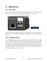
Page 9: ...sent you should see the pixels turn on 4 2 Indicator LEDs Each fuse is paired with a green LED which indicates the condition of the fuse If the fuse is good the LED will be on If the fuse has been blown or is not connected the LED will be off This feature offers a quick method for determining the state of each fuse however in environments where these LEDs are needed to be turned off a switch is lo...

Page 10: ...n the transmitter device and may vary depending on the pixel capacity of the specific device The refresh rate of the pixels will depend on the operating frequency of the specific pixel chip type Refer to the user manual of the PixLite Transmitter device for more information about this topic as the Transmitter will be responsible for the refresh rate of this receiver ...

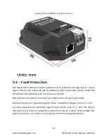
Page 11: ...e R2F S receiver Parameter Value Range Units Input Voltage Range 5 24 V DC Max Current 15 A Max Logic Current Consumption 150 mA Ambient Operating Temperature 20 to 55 C Maximum Current Per Pixel Output 7 5 A 5 2 Mechanical Specifications The PixLite R2F S receiver has dimensions as below Dimension Metric Imperial Length 95mm 3 7 Width 78mm 3 1 Height 33mm 1 3 Weight 0 2kg 0 4lbs ...

Page 12: ...able to withstand installation and operation even in harsh environments ESD protection is present on all data input lines and on all pixel output lines The data input port is protected against shorts to external voltages of up to 24V All pixel output lines are protected against direct shorts of up to 24V This means that even if your pixels or wiring have a fault that causes a direct short between ...

Page 13: ... S User Manual V200702 The PixLite R2F S itself is protected against damage from reversed polarity power input However it does not provide external reverse polarity protection for any loads that you may have connected to the pixel outputs ...

Page 14: ... tab Also check the physical wiring and pinout of the pixels as well as the output fuses Ensure that the green fuse good indicator LEDs under the lid compartment are all visible one per output channel If any are off replace any blown output fuses as required 6 3 Other Issues For the latest more specific troubleshooting information and other help you should refer to our online knowledgebase here ww...

Page 15: ...ipment has been tested and found to comply with the limits for a Class A digital device pursuant to part 15 of the FCC Rules These limits are designed to provide reasonable protection against harmful interference when the equipment is operated in a commercial environment This equipment generates uses and can radiate radio frequency energy and if not installed and used in accordance with the instru...

Reviews: