background image

WISE-6610 Series User Manual

69

4.1

Enabling the LoRaWAN and Network Server

1.

Login WISE-6610 Series. See “Access Interface” on page 14.

2.

Go to 

Customization

 > 

User Modules

.

3.

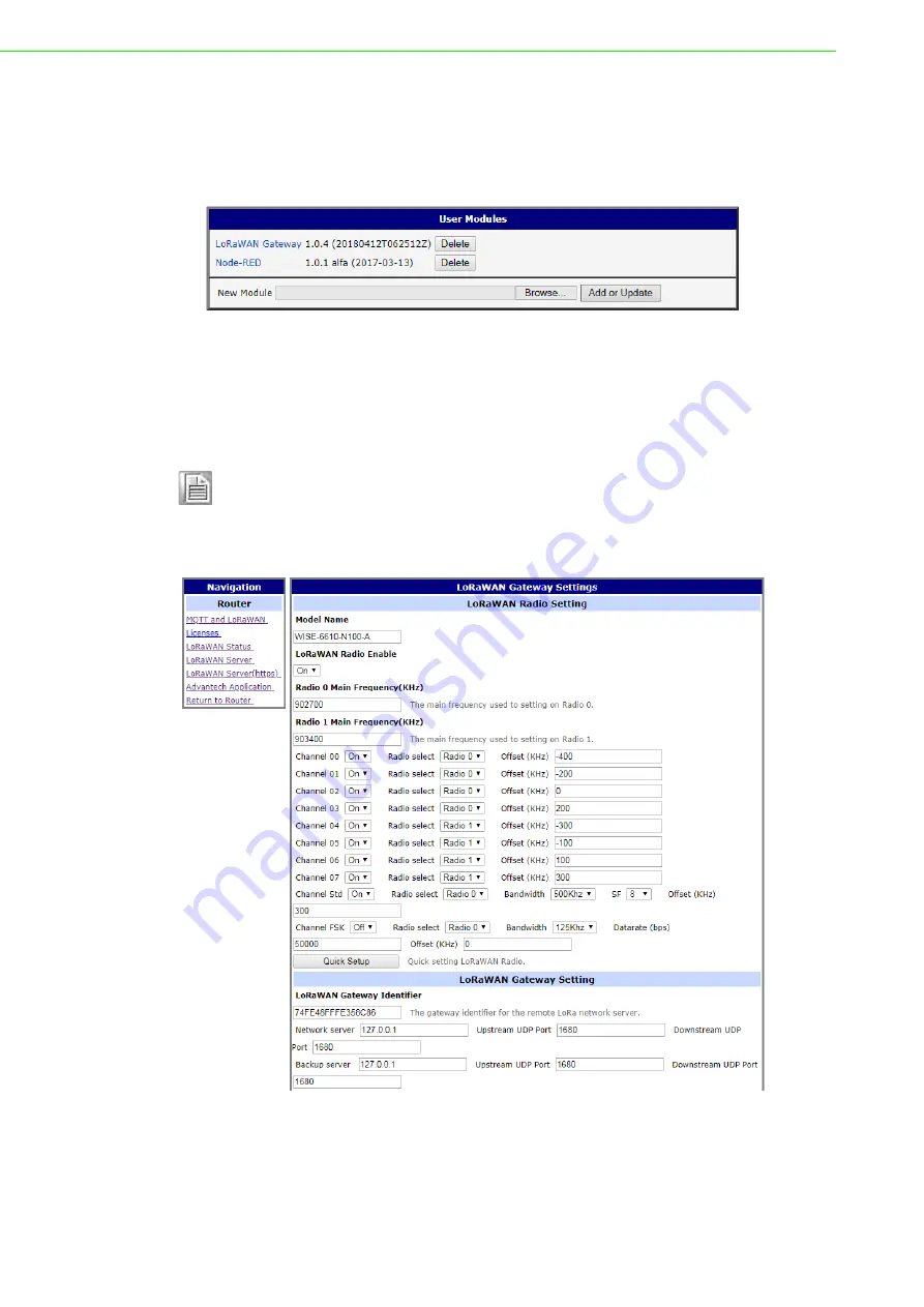
A list of available devices display. Click on the target 

LoRaWAN Gateway

.

Figure 4.1 Customization > User Modules

4.

The Settings menu displays. In 

LoRaWAN Radio Enable

, click the drop-down 

menu to enable LoRaWAN function.

5.

Configure the main frequency for radio 0 and radio 1. For radio 1, there are eight 
channels and one standard channel.

3.

In 

LoRaWAN Gateway Identifier

, copy the gateway ID and set on LoRaWAN 

network server.

Figure 4.2 LoRaWAN Gateway > MQTT and LoRaWAN

Note!

1.

The offset setting for the eight channels must be +/-500KHz.

2.

Use Quick Setup to define the main frequency for receiving the 
data from the LoRaWAN node.

Summary of Contents for WISE-6610 Series

Page 1: ...User Manual WISE 6610 Series Indsutrial LoRaWAN Gateway...

Page 2: ...llation Advantech assumes no liability under the terms of this warranty as a consequence of such events Because of Advantech s high quality control standards and rigorous testing most of our customers...

Page 3: ...tion of this equipment in a residential area is likely to cause harmful interference in which case the user will be required to correct the interference at his own expense This device complies with P...

Page 4: ...anger of a new battery exploding if it is incorrectly installed Do not attempt to recharge force open or heat the battery Replace the battery only with the same or equivalent type recommended by the m...

Page 5: ...any liquid into an opening This may cause fire or electrical shock Never open the equipment For safety reasons the equipment should be opened only by qualified service personnel If one of the followi...

Page 6: ...en Zeitraum nicht benutzt sollten Sie es vom Stromnetz trennen Somit wird im Falle einer berspannung eine Besch digung vermieden Durch die L ftungs ffnungen d rfen niemals Gegenst nde oder Fl ssigkeit...

Page 7: ...n period The following guidelines are also recommended Wear a grounded wrist or ankle strap and use gloves to prevent direct contact to the device before servicing the device Avoid nylon gloves or wor...

Page 8: ...2 2 5 Power Supply Installation 12 Chapter 3 Managing Gateway 13 3 1 Access Interface 14 3 2 Recommended Practices 15 3 2 1 Changing Default Password 15 3 3 Status 16 3 3 1 General 16 3 3 2 Network 17...

Page 9: ...43 User Manual 3 6 7 Update Firmware 66 3 6 8 Reboot 67 Chapter 4 Configuration in Typical Situations 68 4 1 Enabling the LoRaWAN and Network Server 69 4 2 Changing the Raw LoRa Data Format 86 4 3 Nod...

Page 10: ...work Topology 26 Figure 3 16 IPv6 Dynamic DHCP Server Network Topology 26 Figure 3 17 LAN Configuration for an IPv6 Dynamic DHCP Server Network Topology 27 Figure 3 18 Configuration NAT 28 Figure 3 19...

Page 11: ...oRaWAN Server Infrastructure Networks 72 Figure 4 8 LoRaWAN Server Infrastructure Network Create General 73 Figure 4 9 LoRaWAN Server Infrastructure Network Create ADR 74 Figure 4 10 LoRaWAN Server In...

Page 12: ...Chapter 1 1Product Overview...

Page 13: ...rigger Reset button Physical Protection Class IP30 Installation DIN rail wall Dimensions W x H x D 150 x 37 5 x 83 mm 5 9 x 1 48 x 3 27 Weight 500 g 17 63 oz Environment Operating Temperature 40 75 C...

Page 14: ...el See System LED Panel on page 4 for further details 2 I O Power socket Connect cabling for power 3 ETH port RJ45 x 1 4 Antenna connector Connector for antenna LoRa ETH PWR DAT WAN WISE 6610 I O 3 4...

Page 15: ...ries User Manual 1 2 4 System LED Panel 1 3 Dimensions Figure 1 4 System LED Panel LED Name LED Color Description PWR Green DAT Green WAN Green 37 50 1 47 125 40 4 94 140 5 51 150 5 90 83 3 26 7 50 0...

Page 16: ...Chapter 2 2Gateway Installation...

Page 17: ...e system or connect or disconnect cables during periods of lightning activity Caution Before performing any of the following procedures disconnect the power source from the DC circuit Caution Read the...

Page 18: ...eet Make sure airflow around the switch and respective vents is unrestricted With out proper airflow the switch can overheat To prevent performance degredation and damage to the switch make sure there...

Page 19: ...enna connectors in a clockwise direc tion Figure 2 1 Installing the Antenna 2 Position the antenna for optimal signal strength Figure 2 2 Positioning the Antenna Note The location and position of the...

Page 20: ...mounting locations to mark the location of the screw holes 2 If necessary first drill pilot holes Drill four holes over the four marked locations on the wall On concrete it is recommended to install...

Page 21: ...sure that the top of the DIN rail clip hooks over the top of the DIN rail as shown in the following illustration Make sure the DIN rail is inserted behind the spring mechanism 4 Once the DIN rail is s...

Page 22: ...3 2 Removing the DIN Rail Mounting Kit 1 Ensure that power is removed from the SmartSwarm and disconnect all cables and connectors from the front panel of the SmartSwarm 2 Push down on the top of the...

Page 23: ...g Connector Pin Position Maximum cable length 100 meters 328 ft for 10 100BaseT 2 5 Power Supply Installation 1 Insert the power cable into the power socket The cable locks in place if installed corre...

Page 24: ...Chapter 3 3Managing Gateway...

Page 25: ...ace You can change the default password after a successfully log in See Changing Default Password on page 15 4 Click Login to enter the management interface Figure 3 1 Login Screen When you successful...

Page 26: ...n keeping with good management and security practices it is recommended that you change the default password as soon as the WISE 6610 Series is functioning and setup correctly The following details th...

Page 27: ...Ports and System Information If the device is WiFi equipped there will be a WiFi section IPv6 Address item can show multiple different addresses for one network interface This is standard behavior sin...

Page 28: ...Network 3 3 3 DHCP Information about the DHCP server activity is accessible via DHCP item The DHCP server provides automatic configuration of the client devices connected to the device The DHCP serve...

Page 29: ...DynDNS Refer to www dyndns org for more information on how to configure a Dynamic DNS client You can use the following listed servers for the Dynamic DNS service It is possible to use the DynDNSv6 se...

Page 30: ...the first file is overwritten with a new file The Syslogd program will output the system log It can be started with two options to modify its behavior Option S followed by decimal number sets the max...

Page 31: ...uration page is divided into IPv4 and IPv6 columns see Figure 3 10 There is dual stack support of IPv4 and IPv6 protocols they can run alongside you can configure either one of them or both If you con...

Page 32: ...ion of an IP address from a DHCP server in LAN network enabled The device allows automatic allocation of an IP address from a DHCP server in LAN network IP Address A fixed IP address of the Ethernet i...

Page 33: ...P addresses that correspond to the MAC addresses of connected clients If IPv6 column is filled in the DHCPv6 server is used it is dual stack IPv4 and IPv6 Default Gateway Specifies the IP address of a...

Page 34: ...ted to the DHCP clients Use proper IP address notation in IPv4 and IPv6 column Lease time Time in seconds that the IP address is reserved before it can be re used Item Description Enable static DHCP l...

Page 35: ...is 192 168 1 20 DNS server IP address is 192 168 1 20 Figure 3 12 IPv4 Dynamic DHCP Network Topology Item Description Enable IEEE 802 1X Authentication Tick the radio button to enable the authenticati...

Page 36: ...twork Typology Example 2 IPv4 Dynamic and Static DHCP server The range of allocated addresses is from 192 168 1 2 to 192 168 1 4 The address is allocated for 600 seconds 10 minutes The client with the...

Page 37: ...igure Figure 3 15 LAN Configuration for an IPv4 Dynamic and Static DHCP Network Topology Example 3 IPv6 Dynamic DHCP Server The range of dynamic allocated IPv6 addresses is from 2001 db8 1 to 2001 db8...

Page 38: ...WISE 6610 Series User Manual 27 Figure 3 17 LAN Configuration for an IPv6 Dynamic DHCP Server Network Topology...

Page 39: ...the same meaning in the IPv4 NAT Configuration and IPv6 NAT Configuration forms To access this page click Configuration NAT Figure 3 18 Configuration NAT The router actually uses Port Address Translat...

Page 40: ...em Never enable the HTTP item only to access the web configuration from the Internet configuration would not be accessible from the Internet Always check the HTTPS item or HTTPS and HTTP items togethe...

Page 41: ...for Example 1 Example 2 IPv4 NAT Configuration with More Equipment Connected In this example using the switch you can connect more devices behind the router Every device connected behind the router h...

Page 42: ...ries User Manual 31 remaining incoming packets to default server is inactive the router denies connection attempts Figure 3 21 Topology for NAT Configuration Example 2 Figure 3 22 NAT Configuration fo...

Page 43: ...ws you to create a secure connection between two separate LAN networks The device allows you to create up to four OpenVPN tunnels IPv4 and IPv6 dual stack is supported To access this page click Config...

Page 44: ...Pv6 tunnel only Remote IPv6 Subnet Specify the subnet associated with the listed remote interface Remote IPv6 Subnet Prefix Length IPv6 address and prefix of the remote IPv6 network Equivalent of the...

Page 45: ...can use for the username password and X 509 Certificate authentication modes DH Parameters Specifies the protocol for the DH parameters key exchange which you can use for X 509 Certificate authentica...

Page 46: ...vice versa To access this page click Configuration IPSec Remote IP Address 10 0 0 2 10 0 0 1 Remote Subnet 192 168 2 0 192 168 1 0 Remote Subnet Mask 255 255 255 0 255 255 255 0 Local Interface IP Ad...

Page 47: ...36 WISE 6610 Series User Manual Figure 3 25 Configuration 1st Tunnel...

Page 48: ...a local network or IPv6 prefix single number 0 to 128 Local Protocol Port Specifies Protocol Port of a local network The general form is protocol port for example 17 1701 for UDP protocol 17 and port...

Page 49: ...oup number see IKE DH Group Key Lifetime Lifetime key data part of tunnel The minimum value of this parameter is 60 s The maximum value is 86400 s IKE Lifetime Lifetime key service part of tunnel The...

Page 50: ...Configuration in IPv4 Network Figure 3 26 Topology of Configuration Example tunnel configuration Examples of different options for configuration and authentication of tunnel can be found in the appli...

Page 51: ...ubnet Mask Specifies the mask of the network behind the remote side of the tunnel Local Interface IP Address IP address of the local side of the tunnel Remote Interface IP Address IP address of the re...

Page 52: ...he L2TP Tunnel Configuration page click L2TP in the Configuration section of the main menu The L2TP tunnel function allows you to create a password protected connection between 2 LAN networks The devi...

Page 53: ...of the server Client Start IP Address IP address to start with in the address range The range is offered by the server to the clients Client End IP Address The last IP address in the address range Th...

Page 54: ...1 1 N A Remote IP Address N A N A Remote Subnet 192 168 2 0 192 168 1 0 Remote Subnet Mask 255 255 255 0 255 255 255 0 Username username username Password password password Note PPTP is an unencrypted...

Page 55: ...s In order for DynDNS to function you require a public IP address either static or dynamic and an active Remote Access service account at www dyndns org Register the custom domain third level and acco...

Page 56: ...ame Username for logging into the DynDNS server Password Password for logging into the DynDNS server IP Mode Specifies a DynDNS service other than the www dyndns org Possible other services www spdns...

Page 57: ...acts as a NTP client This means that the device automatically adjusts the internal clock every 24 hours To access this page click Configuration Services NTP Figure 3 36 Configuration Services NTP Item...

Page 58: ...bout the device and its expansion ports to a management station To open the SNMP page click SNMP in the Configuration section of the main menu SNMP Simple Network Management Protocol provides status i...

Page 59: ...S status Selecting Enable reporting to supervisory system and entering the IP Address and Period lets you send statistical information to the monitoring system R SeeNet Each monitored value is uniquel...

Page 60: ...the OID in the following manner iso org dod internet private enterprises conel This means that the device provides for example information about the internal temperature OID 1 3 6 1 4 1 248 40 1 3 3 o...

Page 61: ...0 SNMP Configuration Example Figure 3 41 MIB Browser Example In order to access a particular device enter the IP address of the SNMP agent which is the device in the Remote SNMP agent field The dialog...

Page 62: ...artup script The Startup Script dialog is located in Scripts in the Configuration section of the main menu The device also allows you to send e mails using an SSH connection Use the email command with...

Page 63: ...or more examples of Scripts and possible commands see the Application Note Commands and Scripts 1 To access this page click Configuration Scripts 3 4 9 1 Startup Script Use the Startup Script window t...

Page 64: ...wn There is independent IPv4 and IPv6 dual stack implemented in the device so there is independent IPv4 and IPv6 Up Down script IPv4 Up Down Script runs only on the IPv4 WAN connection established los...

Page 65: ...ion updates from a HTTP S or FTP S server IPv6 sites servers are supported Used protocol is specified by an address in Base URL field HTTP HTTPS FTP or FTPS To prevent possible unwanted manipulation o...

Page 66: ...low Unit ID Name of configuration name of the file without extension If the Unit ID is not filled the MAC address of the device is used as the filename the delimiter colon is used instead of a dot Upd...

Page 67: ...com 00 11 22 33 44 55 cfg Figure 3 49 Example of Automatic Update 2 3 5 Customization 3 5 1 Adding a Module You may run custom software programs in the device to enhance the features of the device Us...

Page 68: ...he specified time HTTP Authentication Adds the process of authentication to a server that doesn t provide this service HTTP Authentication Adds support of dynamic protocols PIM SM Adds support of mult...

Page 69: ...the Quick Setup menu enabling the selection of pre configured region specific radio frequency settings LoRaWAN Gateway Setting LoRaWAN Gateway Identifier Displays the gateway identifier for the remote...

Page 70: ...able bridging to a remote MQTT broker MQTT Bridge Port Enter a value to specify the port of MQTT bridge default 1883 MQTT Bridge Address Enter a value to specify the bridge address of the MQTT bridge...

Page 71: ...page use the following guidelines 1 From the LoRaWAN router Customization menu click User Modules 2 In User Modules click the LoRaWAN Gateway link 3 The LoRaWAN Gateway Settings menu displays Under R...

Page 72: ...LoRaWan Server is a ready to use solution which includes a web based user interface providing the components needed to build networks To access this page click User Modules LoRaWAN Gateway LoRaWAN Ser...

Page 73: ...LoRaWAN Gateway LoRaWAN Server https 3 5 1 6 Advantech Application To access this page click User Modules LoRaWAN Gateway Advantech Application For more details see Changing the Raw LoRa Data Format o...

Page 74: ...allowed to log in to the device neither web interface nor SSH Change Password Allows you to change the password for the corresponding user Delete Deletes the corresponding user account Warning If you...

Page 75: ...es Profiles can be used to switch between different modes of operation of the device such as PPP connection VPN tunnels etc It is then possible to switch between these settings using the front panel b...

Page 76: ...stration Set Real Time Clock Figure 3 59 Administration Set Real Time Clock 3 6 5 Backup Configuration You can save the configuration of the device using the Backup Configuration function If you click...

Page 77: ...g messages The progress is shown in the form of adding dots After the firmware update the device will automatically reboot Starting with FW 5 1 0 a mechanism to prevent multiple startups of the firmwa...

Page 78: ...6610 Series User Manual 67 3 6 8 Reboot To reboot the device select the Reboot menu item and then press the Reboot button To access this page click Administration Reboot Figure 3 62 Administration Re...

Page 79: ...Chapter 4 4Configuration in Typical Situations...

Page 80: ...menu displays In LoRaWAN Radio Enable click the drop down menu to enable LoRaWAN function 5 Configure the main frequency for radio 0 and radio 1 For radio 1 there are eight channels and one standard...

Page 81: ...aWAN Network Server Setting click the drop down menu to enable LoRaWAN network server 5 In MQTT Broker Enable click the drop down menu to enable MQTT broker Figure 4 3 LoRaWAN Gateway MQTT and LoRaWAN...

Page 82: ...ot to log into the LoRaWAN Network Server page Figure 4 4 LoRaWAN Gateway LoRaWAN Server 8 Click Infrastructure Gateways to enter the Gateways List page 9 Click Create to add a new gateway Figure 4 5...

Page 83: ...erver Infrastructure Networks Item Description MAC Enter the LoRaWAN gateway ID shown on MQTT and LoRaWAN menu Group Enter the opaque string with application specific settings TX Chain Enter a value t...

Page 84: ...Region Enter a value to determine the regional characteristics of LoRaWAN Coding Rate Enter a value to define the coding rate It is regularly set on 4 5 RX1 Join Delay s Enter a value to define the JO...

Page 85: ...ata Rate SF7 125 kHz SF8 500 kHz SF7 125 kHz SF7 125 kHz SF8 500 kHz SF7 125 kHz SF7 125 kHz SF7 125 kHz SF7 125 kHz SF7 125 kHz Initial RX1 DR Offset 0 0 0 0 0 0 0 0 0 0 Initial RX2 DR SF12 125 kHz S...

Page 86: ...te with the end device on the first reception slot RX1 Initial RX2 DR Enter a value to define the data rate for the second reception slot RX2 Initial RX2 Freq MHz Enter a value to define the default f...

Page 87: ...r Received frame sequence number port Integer LoRaWAN port number data Hex String Raw application payload encoded as a hexadecimal string datetime ISO 8601 Timestamp using the server clock freq Number...

Page 88: ...andlers Create Item Description Application Enter the name of the handler Uplink Fields Enter the filter values to be forwarded to the backend connector Payload Enter the filter values as the format f...

Page 89: ...menu to define when the downlinks may be dropped Never All class A downlinks for a device will be queued and eventu ally delivered All confirmed downlinks will be retransmitted until acknowl edged eve...

Page 90: ...target host which can be mqtt for MQTT or mqtts for MQTT SSL Publish Uplinks Enter a string to define a server pattern for constructing the publication topic for uplink messages including the actual...

Page 91: ...rofiles Create General Failed Click the drop down menu to select the flag indicates the failure items badarg Some connector parameters are bad network The destination server cannot be reached topic Th...

Page 92: ...vice security TX Window Click the drop down menu to select the TX window for downlinks to the device Auto Choose the earliest feasible option RX1 or RX2 RX1 Always use the first RX window RX2 Always u...

Page 93: ...Nodes Create Set RX1 DR Offset Enter a value to define the offset between the uplink and the RX1 slot downlink data rates Set RX2 DR Enter a value to define the data rate for the second reception slot...

Page 94: ...to define the frame counter FCnt Down Enter a value to define the frame counter Submit Click Submit to save the values and update the screen Item Description DevEUI Enter the DevEUI for the device Pr...

Page 95: ...ed Click Received Frames to enter the Received Frames page and check the received messages Figure 4 23 LoRaWAN Server Received Frames 27 Since the MQTT broker on the WISE 6610 series is enabled by def...

Page 96: ...WISE 6610 Series User Manual 85 Figure 4 25 MQTT Subscription 28 Click Infrastructure Events to enter the Events List page to view the events Figure 4 26 LoRaWAN Server Infrastructure Events...

Page 97: ...WAN Gateway Advantech Application Figure 4 27 User Modules LoRaWAN Gateway Advantech Application 2 Click Detail to list the real data and status detail of the node Figure 4 28 Data and Status Note WIS...

Page 98: ...s shown in the figure below Figure 4 29 User Modules LoRaWAN Gateway MQTT and LoRaWAN 4 Click LoRaWAN Server Devices Activated Nodes to enter the Nodes List page Figure 4 30 LoRaWAN Server Activated N...

Page 99: ...Other Software Applications 4 3 Node RED Setup 1 Go to Customization User Modules 2 A list of available devices display Click on the target Node RED Figure 4 33 Customization User Modules 3 The Setti...

Page 100: ...tions are subject to change without notice No part of this publication may be reproduced in any form or by any means electronic photocopying recording or otherwise without prior written permis sion of...

Reviews: