background image

TPC-1240 User’s Manual

6

Figure 1.1: I/O Ports arrangement

1.7  Mounting

1.There is a piece of adhesive waterproof gasket on the plastic front 

bezel. Make sure the waterproof gasket is in position before install the 
TPC-1240 to the panel opening.

2.Install the TPC-1240 to the panel opening.
3.Find the eight clamps and eight long screws in the accessory pack. 

Hook those clamps to those holes around the four sides of the bezel. 
Insert the screws to every clamp and fasten them. These screws will 
then push on the mounting panel and fix the unit.

4.The mounting panel thickness is suggested to be less than 6 mm (0.236 

inch).

Figure 1.2: Panel mounting

Summary of Contents for TPC-1240

Page 1: ...TPC 1240 RISC based operator interface terminal with 12 1 flat panel display Users Manual ...

Page 2: ...rmation provided in this manual is intended to be accurate and reliable However Advantech Co Ltd assumes no responsibility for its use nor for any infringements upon the rights of third parties which may result from its use Acknowledgements TPC 1240 is a trademark of Advantech Co Ltd IBM PC AT and PS 2 are trademarks of International Business Machines Corporation MS DOS and Windows CE are trademar...

Page 3: ... uses and can radiate radio frequency energy If not installed and used in accordance with this user s manual it may cause harmful interference to radio communications Operation of this equip ment in a residential area is likely to cause harmful interference in which case the user will be required to correct the interference at his own expense Warning Any changes or modifications made to the equipm...

Page 4: ...urce CD x 1 piece 2 Additional Information and Assistance 1 Visit the Advantech web site at www advantech com where you can find the latest information about the product 2 Contact your distributor sales representative or Advantech s customer service center for technical support if you need additional assistance Please have the following information ready before you call Product name and serial num...

Page 5: ...me disconnect it from the power source to avoid damage by transient overvoltage 12 Never pour any liquid into an opening This may cause fire or electrical shock 13 Never open the equipment For safety reasons the equipment should be opened only by qualified service personnel 14 If one of the following situations arises get the equipment checked by service personnel a The power cord or plug is damag...

Page 6: ...t über einen längeren Zeitraum nicht benutzt sollten Sie es vom Stromnetz trennen Somit wird im Falle einer Überspannung eine Beschädi gung vermieden 12 Durch die Lüftungsöffnungen dürfen niemals Gegenstände oder Flüssigkeiten in das Gerät gelangen Dies könnte einen Brand bzw elektrischen Schlag aus lösen 13 Öffnen Sie niemals das Gerät Das Gerät darf aus Gründen der elektrischen Sicherheit nur vo...

Page 7: ...Opening the box 10 Figure 2 2 Unpacking the unit 10 Figure 2 3 Power connector and power lines 11 Figure 2 4 Power connector pin assignment 12 Figure 2 5 Plug in the power lines and turn on the power switch12 Chapter 3 The Engine of the TPC 1240 13 3 1 Passive backplane 14 3 2 CPC 1110 main board 14 Table 3 1 CPC 1110 main board connector jumper list 14 Table 3 2 Connector pin assignments 14 3 3 T...

Page 8: ...e 4 16 Direct connection 32 Figure 4 17 default settings 32 Figure 4 18 Default settings cont 33 Figure 4 19 Web browser on TPC 1240 33 4 4 Application program development 33 Figure 4 20 Flowchart of building Windows CE runtime 35 Chapter 5 Linux in the TPC 1240 37 5 1 Technology 38 Figure 5 1 Structure of iCava 39 5 2 Linux components on the TPC 1240 40 5 3 Boot Up the TPC 1240 with Linux 40 Chap...

Page 9: ...eplacement 52 Figure 7 4 Replace the fuse 52 Appendix A Fuse Specifications 53 A 1 Supported Input Timing Modes 54 Appendix B Registry searching sequence of TPC 1240 55 B 1 Supported Input Timing Modes 56 Figure B 1 Windows CE registry searching algorithm flow chart56 ...

Page 10: ...iv ...

Page 11: ...al Information This chapter gives background information on the TPC 1240 Sections include Introduction Specifications LCD Specifications Touchscreen specifications Power I O ports Mounting Exploded diagram Dimensions and cutout C H A PT E R ...

Page 12: ...40 offers cost effective solution for operator interface terminals With proper application programs it would give a comfortable graphic user interface GUI at this size of display Fan less and modular CPU board the introduction of low power pro cessor prevents this system from unreliable fans In addition the mod ular design facilitates the maintenance or possible upgrade on the CPU board Powerful c...

Page 13: ... 1240 does not provide floppy disk interface 1 2 2 I O Ports 3 serial ports 9 pin RS 232 COM1 RS 485 COM2 and 2 pin RS 232 COM3 1 RJ 45 Ethernet port 1 2 3 Storage The primary storage device is the 16 MB built in flash memory The default Windows CE or Linux operating system is in this device The TPC 1240 provides one CompactFlash card slot This slot is for the storage of variety of Windows CE Linu...

Page 14: ...n 1 3 LCD Specifications Table 1 1 LCD specifications Display Type TFT color LCD Size Diagonal 12 1 MaximumResolution 800 x 600 SVGA MaximumColors 256k Pixel pitch WxH mm 0 31 x 0 31 Viewing angle 100 Luminance cd m2 300 Contrast ratio 150 minimum Operating temperature o C 0 50 ambient VR control Brightness adjustable Backlight 2 CCFL Backlight MTTF 50 000 hours ...

Page 15: ...ngement The TPC 1240 has 3 serial ports 1 RJ 45 LAN port The arrangement of these ports is shown in Figure 1 1 Note In spite of the stated input voltage rating the TPC 1240 can operate using 18 30 VDC Type Resistive Base glass construction Tempered Glass Resolution Continuous Light transmission 75 typical Controller PS 2 interface simulated by SPI Power rating 3 3 to 5 VDC Software driver Windows ...

Page 16: ...40 to the panel opening 2 Install the TPC 1240 to the panel opening 3 Find the eight clamps and eight long screws in the accessory pack Hook those clamps to those holes around the four sides of the bezel Insert the screws to every clamp and fasten them These screws will then push on the mounting panel and fix the unit 4 The mounting panel thickness is suggested to be less than 6 mm 0 236 inch Figu...

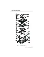
Page 17: ...7 Chapter 1 General Information 1 8 Exploded diagram Figure 1 3 Exploded diagram ...

Page 18: ...TPC 1240 User s Manual 8 1 9 Dimensions and cutout Weight 2 2 kg without HDD Dimension 311 x 237 x 50 mm W x H x D Cutout 302 x 228 mm suggested Figure 1 4 Dimensions and cutout ...

Page 19: ...9 Chapter 2 System Quick Starting 2 System Quick Starting This chapter provides a brief explanation for operating the TPC 1240 C H A PT E R ...

Page 20: ...packing and Powering up Step 1 Unpack the TPC 1240 from its packaging Please check the packing list at the beginning of this manual Figure 2 1 Opening the box Figure 2 2 Unpacking the unit Accessory Box P N 2110002150 Cushions P N 2130201590 Main Box P N 2110002430 ...

Reviews: