86
2.10 LPC and eSPI Interface
*SOM-5992 is not support eSPI.
The Module LPC and eSPI interfaces share connector pins. A Module design
may
support
either LPC or eSPI or both, at the Module vendor’s discretion. Module pin ESPI_EN# is available for the
Carrier to signal to the Module whether LPC or eSPI is to be used. The Carrier
shall
leave the ESPI_EN#
unconnected on the Carrier for LPC operation. The Carrier
shall
tie ESPI_EN# to GND for eSPI
operation. The Module
shall
terminate ESPI_EN# as appropriate to facilitate this.
The LPC bus is a 3.3V bus and eSPI is a 1.8V bus. There is the possibility of a mismatch – an eSPI only
Module mated with a LPC only Carrier, or an LPC only Module on an eSPI Carrier. Module designers
should
protect the Module eSPI interface against accidental exposure to 3.3V Carrier LPC signals.
Carrier designers
should
protect a Carrier eSPI interface against accidental exposure to 3.3V Module
LPC signals. In both cases, a simple and low cost protection scheme
may
be realized with low value
in-line series resistors (typically 33 ohms) and BAT54 Schottky diodes on each line. The diode anode is
tied to the eSPI device pin and the cathode to the 1.8V supply rail. Ideally, that 1.8V supply rail can sink
current. In the event of a mismatch, the offending (Module or Carrier) 3.3V rail is discharged through the
series resistor and the Schottky diode to the (Carrier or Module) 1.8V rail and not through the eSPI
device.
2.10.1 LPC /eSPI Signal Definition
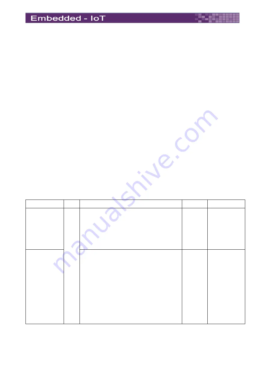
Table 30
: LPC/eSPI Interface Signal Definition
Signal
Pin# Description
I/O
Note
LPC_SERIRQ
A50
LPC serialized IRQ.
Carrier Board:
Connect to
LPC - SERIRQ
N/C if not used
I/O 3.3V
CMOS
ESPI_CS1#
ESPI Mode: eSPI Master Chip Select Outputs
Driving Chip Select# A low selects a particular
eSPI slave for the transaction. Each of the
eSPI slaves is connected to a dedicated Chip
Selectn# pin.
Carrier Board:
Connect to
eSPI Device – eSPI_CS1#
N/C if not used
O 1.8V
Suspend
/ 1.8V
2


