background image

HPC-7120S User Manual

/ 用户手册

18

When the system power is on and the SATA HDD is well connected, the activity LED
glows steady green. If it fails to light up, check the SATA connection. Or please ask a
technician to inspect the related cables in the chassis.

当系统电源接通且 SATA HDD 连接良好时,Activity LED 为绿灯亮。如果灯未亮,请
检查是否已将 SATA HDD 连接好。或者请咨询技术人员检查机箱内电缆是否连接好。

當系統電源接通且 SATA HDD 連接良好時,Activity LED 為綠燈亮。如果燈未亮,請
檢查是否已將 SATA HDD 連接好。或者請諮詢技術人員檢查主機殼內電纜是否連接好。

3.2

The Rear Panel

/ 后面板 / 後面板

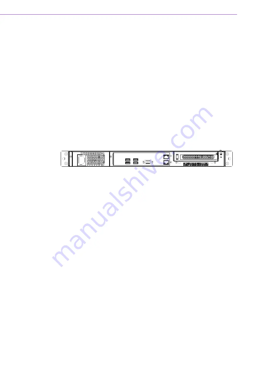
The rear plate includes 1-slot I/O bracket


and a motherboard I/O opening. (see Fig-

ure 3.3).

后面板带有 1 槽 I/O 支架和 1 个母板 I/O 开口 (如图 3.3 所示)。

後面板帶有 1 槽 I/O 支架和 1 個主機板 I/O 開口 (如圖 3.3 所示)。

Figure 3.2 Rear Panel (default) 

/ 后面板 / 後面板

There is a ground screw with a washer located on the lower right of the rear panel; 
when properly grounded, it protects the system in case of electric leakage.

后面板的右下方带有 1 个带垫圈的地脚螺钉,可以保护系统免受漏电损坏。

後面板的右下方帶有 1 個帶墊圈的地腳螺釘,可以保護系統免受漏電損壞。

3.3

Replacing the Cooling Fan

/ 更换风扇 / 更換風扇

There are three system cooling fans behind the front plate of the chassis.

机箱带有 3 个系统冷却风扇,分别位于机箱前面板后。

主機殼帶有 3 個系統冷卻風扇,分別位於主機殼前面板後。

3.3.1

Replacing the system cooling fan

/ 更换系统冷却风扇 / 更換系統

冷卻風扇

1.

Unplug fan power connectors. 

2.

Unscrew the 4 screws on the fan bracket. Take out the fan bracket carefully. 
(See Figure 3.4)

3.

Remove the four screws on the failed fan unit and take out the fan. 

4.

Fasten a new fan onto the fan bracket.

5.

Plug in fan power connectors.

Summary of Contents for HPC-7120S

Page 1: ...User Manual HPC 7120S 1U Short depth Server Chassis for ATX MicroATX Motherboard 1U ATX MicroATX 1U ATX MicroATX...

Page 2: ...ed in any form or by any means without the prior written permission of Advantech Co Ltd Information provided in this manual is intended to be accurate and reliable How ever Advantech Co Ltd assumes no...

Page 3: ...F it may damage the equipment 9 The openings on the enclosure are for air convection Protect the equipment from overheating DO NOT COVER THE OPENINGS 10 Make sure the voltage of the power source is c...

Page 4: ...disconnect the power cord from your chassis whenever you work with the hardware Do not make connections while the power is on Sensitive electronic components can be damaged by sudden power surges 20...

Page 5: ...v HPC 7120S User Manual 17 18 FCC 15 1 2 19 20 21 22 CCC 1 2 3 4 5 6 7 8 0 C 32 F 40 C 104 F 9 10 11 12 13 14 15 16 17 18 FCC 15 1 2...

Page 6: ...the best performance possible from your products If you run into technical difficulties we are here to help For the most frequently asked questions you can easily find answers in your product documen...

Page 7: ...t of replacement materials service time and freight Please consult your dealer for more details If you think you have a defective product follow these steps 1 Collect all the information about the pro...

Page 8: ...ntact your distributor or sales repre sentative immediately We have carefully inspected the product mechanically and electrically before shipment It should be free of marks and scratches and in perfec...

Page 9: ...ix HPC 7120S User Manual...

Page 10: ...HPC 7120S User Manual x...

Page 11: ...Figure 2 4 Installing a Motherboard 11 2 3 Installing Disk Drives 11 Figure 2 5 Installing internal HDD HDD HDD 12 2 3 1 Installing SATA HDD in the Mobile HDD tray HDD SATA HDD SATA 12 Figure 2 6 Rem...

Page 12: ...Configuration B 19 Figure 3 5 Optional Rear Configuration B 19 Chapter 4 Dual Slot SATA Backplane SATA SATA 23 4 1 Backplane Layout 24 Figure 4 1 Front side layout connect to the HDD HDD HDD 24 Figure...

Page 13: ...Chapter 1 1 General Information...

Page 14: ...e temperature is inside the chassis A wide range of standard computing peripherals can be integrated with these chassis to accommodate robust applications in rugged environments 24 hours a day 7 days...

Page 15: ...er supply Please see the options below FATX 1U FATX 1U Table 1 1 Power supply options Wattage 350 W max ATX PFC FATX 650 W max ATX PFC 1U Redundant Input rating 100 240 Vac Full range 100 240 Vac Full...

Page 16: ...2 V 0 05 A 5 Vsb 0 1 A MTBF 100 000 hours 25 C Safety UL TUV CB CCC Caution Power supply options are subject to the product datasheet on the Advantech website Table 1 2 Environment specifications Envi...

Page 17: ...5 HPC 7120S User Manual Chapter 1 General Information 1 5 Dimension Diagram Figure 1 1 Dimension diagram...

Page 18: ...HPC 7120S User Manual 6...

Page 19: ...Chapter 2 2 System Setup...

Page 20: ...hassis parts lists HPC 7120S A HPC 7120S A 2 1 Removing the Top Cover To remove the cover please proceed as below 1 Unscrew the seven knurled screws on the top side see Figure 2 1 1 7 2 1 1 7 2 1 Note...

Page 21: ...s located on the top cover see Figure 2 2 It shows the stub copper location for attaching the specific ATX MicroATX Mini ITX motherboard Users can find the stub copper in the accessory box see Figure...

Page 22: ...tor and the 8 pin 4 pin 12 V power connector from the power supply to the motherboard 4 Connect the 9 pin USB wire HDD LED wires LAN LED wire Power switch wire and the system reset switch wire from th...

Page 23: ...LED Figure 2 4 Installing a Motherboard 2 3 Installing Disk Drives The HPC 7120S comes with two easy to maintain 2 5 SATA HDD trays Please refer to the following instructions to install the various d...

Page 24: ...ck the tray Hold the handle of the tray and draw it out from the chassis 2 Slide one SATA disk drive into the proper location in the tray and fix it with 4 screws 3 Return and push the HDD tray into t...

Page 25: ...D SATA HDD 2 4 Attaching the Ears and Handles There are two ears and two handles in the accessory box If you need to install them please refer to Figure 2 11 and simply fasten them to the front right...

Page 26: ...HPC 7120S User Manual 14...

Page 27: ...Chapter 3 3 Operation...

Page 28: ...Press this switch to turn the system power on or off Please use system shutdown or press this switch for few seconds to turn off the sys tem ATX power System Reset button Press this button to reboot...

Page 29: ...TA HDD LED 3 2 Table 3 1 LED Indicator functions LED Description Blue Red Power System Power Normal N A HDD LED Hard Disk Drive Activity Data Access N A LAN LAN1 LAN2 status LAN1 LAN2 LAN1 LAN2 Normal...

Page 30: ...I O 3 3 1 I O 1 I O 3 3 Figure 3 2 Rear Panel default There is a ground screw with a washer located on the lower right of the rear panel when properly grounded it protects the system in case of electr...

Page 31: ...Replacing system fan 3 4 Optional I O Configs I O I O HPC 7120S supports optional I O configurations One such configuration B is depicted below showing front and rear panels HPC 7120S I O I O HPC 7120...

Page 32: ...ower supply bracket and then gently take it out see Figure 3 6 5 Loosen the screws on the rear plate and the screw on the HDD bracket and then gently take it out see Figure 3 6 6 Loosen the screws on...

Page 33: ...21 HPC 7120S User Manual Chapter 3 Operation Figure 3 6 Replacing power supply HDD tray and system fan...

Page 34: ...HPC 7120S User Manual 22...

Page 35: ...Chapter 4 4 Dual Slot SATA Backplane SATA SATA...

Page 36: ...ual 24 4 1 Backplane Layout Only for HPC 7120S 35ZXE HPC 7120S 35ZXE HPC 7120S 35ZXE Figure 4 1 Front side layout connect to the HDD HDD HDD Figure 4 2 Rear side layout connect to the RAID card or mot...

Page 37: ...Appendix A A Exploded Diagram...

Page 38: ...HPC 7120S User Manual 26 A 1 Exploded Diagram Figure A 1 Exploded Diagram...

Page 39: ...27 HPC 7120S User Manual Appendix A Exploded Diagram...

Page 40: ...No part of this publication may be reproduced in any form or by any means electronic photocopying recording or otherwise without prior written permis sion of the publisher All brand and product names...

Reviews: