


251
ADAM-4000 Series User Manual
Ap
pe
nd
ix E
R
S-4
85
N
etw
ork
Because each input is biased to 2.4 V, the nominal common mode voltage of bal
-
anced RS-485 systems, the 18 kΩ on the input can be taken as being in series
across the input of each individual receiver.
If thirty of these receivers are put closely together at the end of the transmission line,
they will tend to react as thirty 36kΩ resistors in parallel with the termination resistor.
The overall effective resistance will need to be close to the characteristics of the line.
The effective parallel receiver resistance RP will therefore be equal to:
R
P
= 36 x 103/30 = 1200 W
While the termination receptor RT will equal:
R
T
= R
O
/ [1 - R
O
/R
P
]
Thus for a line with a characteristic impedance of 100 Ω resistor, the termination
resistor RT should be:
R
T
= 100/[1 - 100/1200] = 110 Ω
Since this value lies within 10% of the line characteristic impedance.
Thus as already stated above the line termination resistor RT will normally equal the
characteristic impedance Z
O
.
The star connection causes a multitude of these discontinuities since there are sev
-
eral transmission lines and is therefore not recommend.
E.4
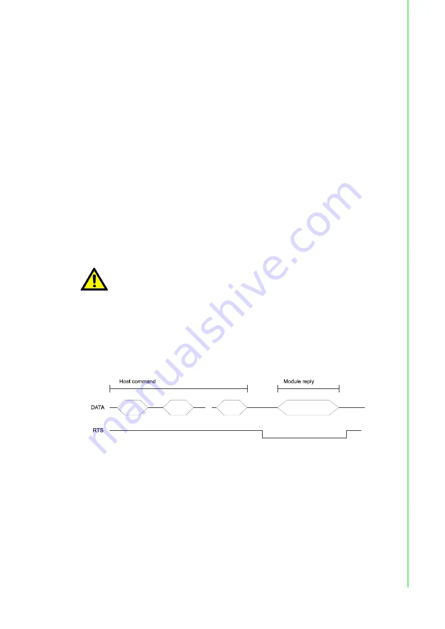
RS-485 Data Flow Control
The RS-485 standard uses a single pair of wires to send and receive data. This line
sharing requires some method to control the direction of the data flow. RTS (Request
To Sent) and CTS (Clear To Sent) are the most commonly used method.
Figure E.6 RS-485 data flow control with RTS
Intelligent RS-485 Control
ADAM-4510 and ADAM-4520 are both equipped with an I/O circuit which can auto
-
matically sense the direction of the data flow. No handshaking with the host (like
RTS, Request to Send) is necessary to receive data and forward it in the correct
direction. You can use any software written for half-duplex RS-232 with an ADAM
network without modification. The RS-485 control is completely transparent to the
user.
Caution!
The recommended wiring method that causes a minimum amount of
reflection is daisy chaining where all receivers tap from one transmis
-
sion line and needs to be terminated only twice.
Summary of Contents for Adam - 4021
Page 1: ...User Manual ADAM 4000 Series Data Acquisition Modules...
Page 4: ...ADAM 4000 Series User Manual iv...
Page 12: ...ADAM 4000 Series User Manual xii...
Page 13: ...Chapter 1 1 Introduction...
Page 16: ...ADAM 4000 Series User Manual 4...
Page 17: ...Chapter 2 2 Installation Guideline...
Page 33: ...Chapter 3 3 I O Modules...
Page 78: ...ADAM 4000 Series User Manual 66...
Page 79: ...Chapter 4 4 Command Set...
Page 99: ...87 ADAM 4000 Series User Manual Chapter 4 Command Set...
Page 100: ...ADAM 4000 Series User Manual 88...
Page 101: ...Chapter 5 5 Analog Input Module Commands...
Page 127: ...Chapter 6 6 Analog Output Module Commands...
Page 144: ...ADAM 4000 Series User Manual 132...
Page 145: ...Chapter 7 7 I O Relay Counter Frequency...
Page 201: ...Chapter 8 8 Calibration...
Page 206: ...ADAM 4000 Series User Manual 194...
Page 207: ...Appendix A A Technical Specifications...
Page 216: ...ADAM 4000 Series User Manual 204 Figure A 5 ADAM 4024 Function Diagram...
Page 232: ...ADAM 4000 Series User Manual 220 Figure A 14 ADAM 4080 Function Diagram...
Page 233: ...Appendix B B Data Formats and I O Ranges...
Page 244: ...ADAM 4000 Series User Manual 232...
Page 245: ...Appendix C C Technical Diagrams...
Page 246: ...ADAM 4000 Series User Manual 234 C 1 ADAM Dimensions Figure C 1 ADAM Modules Dimensions...
Page 248: ...ADAM 4000 Series User Manual 236 Figure C 3 DIN Rail Mounting...
Page 250: ...ADAM 4000 Series User Manual 238 C 2 3 Piggyback Stack Figure C 6 Piggyback Stack...
Page 251: ...Appendix D D Utility Software...
Page 258: ...ADAM 4000 Series User Manual 246...
Page 259: ...Appendix E E RS 485 Network...
Page 264: ...ADAM 4000 Series User Manual 252...
Page 265: ...Appendix F F Using the Checksum Feature...
Page 268: ...ADAM 4000 Series User Manual 256...
Page 269: ...Appendix G G I O Modbus Mapping Table...
Page 283: ...Appendix H H Changing to Modbus Protocol...
Page 285: ...273 ADAM 4000 Series User Manual Appendix H Changing to Modbus Protocol...