MK Series Portable Chiller : Air-Cooled : HE INSTRUMENT
Page: 25
ADVANTAGE ENGINEERING, INC.
525 East Stop 18 Road Greenwood, Indiana 46142
317-887-0729 Fax: 317-881-1277
Service Department Fax: 317-885-8683
Email: [email protected]
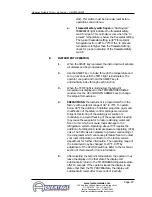
software version number. At this time, the operator can
verify that all lights and digits are functioning properly. If
the operator determines an indicating light or digit does
not illuminate, the instrument must be removed and sent
to the factory for repair.
3.
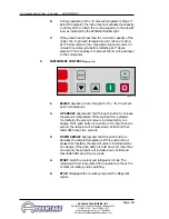
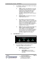
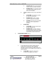
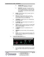
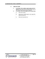
With electrical power supplied to the unit, the POWER light
will illuminate. The display will remain dark with exception
of the WATER LEVEL, PROBE and PHASE lights which will be
‘solid green’ if those conditions are ‘ok’. The FLOW light
will ‘flash red’ to indicate that the pump is not on (not
generating flow). This is the normal “stop” state of the
instrument. If the operator determines the WATER LEVEL,
PROBE and PHASE lights are ‘flashing red’, the operator
must determine the reason and correct:
a.
Water level
: when the reservoir water level is
below the level switch mount, the automatic water
make-up system is activated in an effort to restore
the reservoir to the proper operating level. If the
reservoir does not fill in a reasonable amount of
time, check the operation of the make-up solenoid
valve or determine in the water supply valve
(customer supplied) is fully open. The water level
sight glass is provided to visually check the reservoir
level.
b.
Probe:
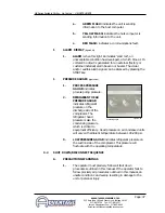
a possible cause of a probe error is the
probe service connection is wet. Locate the 2 pin
(white plug) service connection, open and dry with
compressed air. If this action does not remove the
error indication, inspect the probe wiring, which
could be incorrect or damaged. Probe connections
are at the instrument panel. Correct wiring is (from
top to bottom) ‘white’ - ‘black’ - ‘white’ - ‘black’ -
‘red’ - ‘red’. If the probe connections are correct,
the probe may be faulty and should be replaced.
c.
Phase:
follow the procedure outline in section 3.2
paragraph B ‘Electric Motor Phasing’ to clear a
phase error. If a phase error can not be cleared
even through the pump motor is rotating correctly,
the three phase monitor is defective and should be
replaced. Disconnect the unit until a replacement is
obtained.
4.
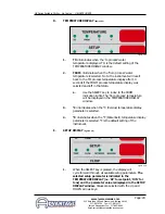
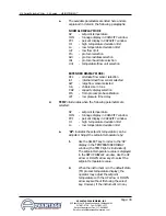
After a ‘flashing red’ indication is diagnosed and repaired,
the ‘flashing red’ indication will turn ‘solid red’. The
operator can clear a ‘solid red’ fault indication by pressing
the START key.
Summary of Contents for Maximum
Page 2: ......
Page 6: ...Page 6 THIS PAGE INTENTIONALLY BLANK ...
Page 44: ...Page 44 THIS PAGE INTENTIONALLY BLANK ...
Page 58: ...Page 58 THIS PAGE INTENTIONALLY BLANK ...
Page 79: ...END 2003 ADVANTAGE ENGINEERING INC RE 1 2 03 ...
Page 80: ......


