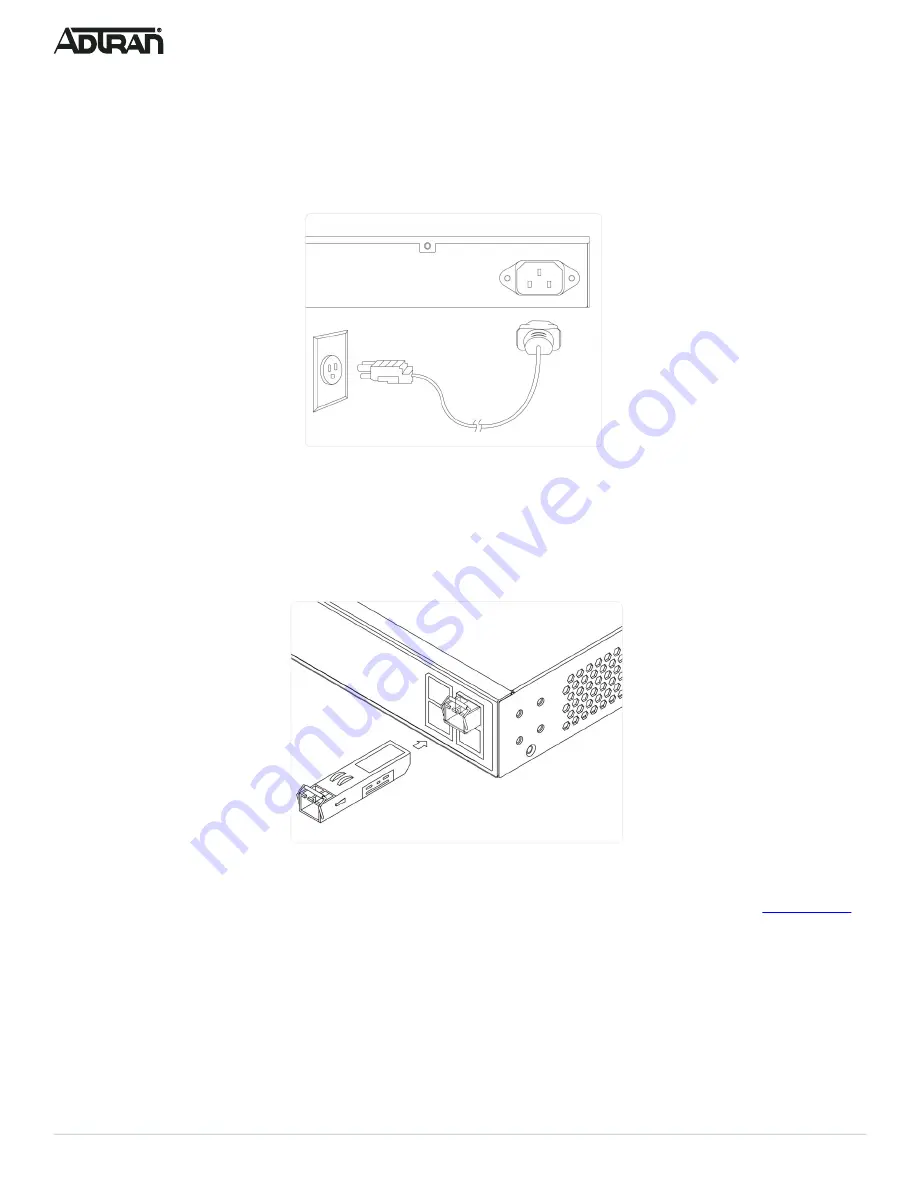
ADTRAN NetVanta 1560-24-740W Quick Start Manual Download Page 4

4

617108124PF2-13D

Connect AC Power

To connect the AC power cord to the switch, complete the following steps.

1. Connect the AC power cord to the AC power receptacle on the rear panel of the switch. 
2. Connect the other end of the AC power cord to a properly grounded AC power outlet. 
3. Confirm that the power is connected properly. The 

SYSTEM

 LED should be ON (see 

“SYSTEM Status LED”

).

Figure 7. Connecting the AC Power Cord

Install SFP+ Modules

You can install or remove a mini-GBIC SFP+ module from a SFP+ port without having to power off the switch. To install an SFP+ module, complete the 

following steps.

1. Insert the module into the appropriate SFP+ port. 
2. Press firmly to ensure that the module seats properly into the connector.

Figure 8. Installing an SFP+ Module into an SFP+ Port

g

     NOTE

This product is intended for use with a Class 1 Laser module that complies with FDA 21 CFR 1040.10, 1040.11 and IEC 60825-1. For continued 

compliance with the above standards, only approved Class 1 laser modules from an ADTRAN approved vendor list (llocated online at 

www.adtran.com

should be installed in this product.  ADTRAN cannot certify system integrity with other laser modules.

Initially Configuring the Switch

The Switch can be configured by two methods:

Web based Graphical User Interface (GUI)

Command Line Interface (CLI)

Initial Switch Configuration Using a Web Browser

After powering up the switch for the first time, you can perform the initial switch configuration using a web browser. 

Summary of Contents for NetVanta 1560-24-740W

Page 1: ...ck mount two brackets and eight screws Quick Start f WARNING The NetVanta 1560 24 740W is intended for indoor use only Ethernet PoE cables and attached equipment are intended for use within the same building with equipotential bonding and not intended to be placed in separate buildings or structures Failure to deploy as described could result in permanent damage from lightning or other electrical ...

Page 2: ...1 Attach the brackets provided in the mounting kit to both sides of the chassis Insert the provided screws and tighten them with a screwdriver to secure the brackets Figure 3 Attaching Brackets to the Switch 2 Place the switch on a rack shelf in the rack Push it in until the oval holes in the brackets align with the mounting holes in the rack posts 3 Secure the brackets to the posts by inserting r...

Page 3: ... and sides of the unit for sufficient air flow Mounting on a Wall To mount the switch on a wall complete the following steps 1 Using the mounting holes on the bottom of the unit as a template install the user supplied screws in the appropriate location on the wall Be aware of the dimensional limitations of the screws Hang the switch on the screws and ensure that it is securely attached f CAUTION T...

Page 4: ...te SFP port 2 Press firmly to ensure that the module seats properly into the connector Figure 8 Installing an SFP Module into an SFP Port g NOTE This product is intended for use with a Class 1 Laser module that complies with FDA 21 CFR 1040 10 1040 11 and IEC 60825 1 For continued compliance with the above standards only approved Class 1 laser modules from an ADTRAN approved vendor list llocated o...

Page 5: ...net Protocol Version 4 TCP IPv4 Then select the Properties button g NOTE Be sure to record all your PC s current IP settings to be able to restore them later Select the radio button Use the following IP address and enter in the IP address for the PC e g any IP address not in use and in between 10 10 10 2 and 10 10 10 254 subnet mask e g 255 255 255 0 Select OK to change the PC s IP address 3 Power...

Page 6: ...larm has been triggered for troubleshooting LINK ACT SPD Mode LED The LINK ACT SPD Mode LED indicates the port status LEDs are displaying in link act speed mode PoE Mode LED The PoE Mode LED indicates the port status LEDs are displaying in PoE mode Port Status LEDs The Port Status LEDs indicate the current status of each port in either Link Act Speed mode or PoE mode By pressing the MODE button fo...

Page 7: ...to a connected device On An abnormal state such as an overload status has been detected in the switch Off The port has no active network cable connected or it is not connected to a PoE powered device Other wise the port may have been disabled through the switch user interface Task Press for System LED Behavior Port Status LED Behavior Change LED Mode 0 2 seconds Solid Green LED status will change ...

Page 8: ...erference received including interference that may cause undesired operation Changes or modifications not expressly approved by ADTRAN could void the user s authority to operate this equipment g NOTE This equipment has been tested and found to comply with the limits for a Class A digital device pursuant to part 15 of the FCC Rules These limits are designed to provide reasonable protection against ...

Reviews: