


8
617101564F1-13A
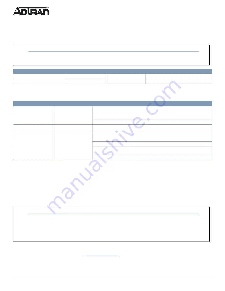
Resetting the Switch
By pressing the
RESET
button for certain period of time, you can perform the following tasks:
■ Reset the switch (to reboot and restore the switch to the previous configuration settings saved)
■ Restore the switch to factory defaults (to restore the original factory default settings to the switch).
Troubleshooting the Switch
The following table provides information to easily troubleshoot problems by taking actions based on the suggested solutions.
Product Specifications
Compliance
■ This device complies with Part 15 of the FCC rules. Operation is subject to the following two conditions:
■ 1. This device may not cause harmful interference.
■ 2. This device must accept any interference received, including interference that may cause undesired operation.
■ Changes or modifications not expressly approved by ADTRAN could void the user's authority to operate this equipment.
■ Changes or modifications not expressly approved by ADTRAN will void the warranty.
■ This equipment contains no parts that can be serviced by the user.
■ This product is NRTL Listed to the applicable UL/CSA Standards. This product has also been evaluated to applicable international standards for CE
marking and RCM marking.
■ This product meets EU RoHS Directive. Refer to
for further information on RoHS/WEEE.
NOTE
g
As seen in the table below, you can easily judge which task is being performed by reading the LED behaviors while pressing and holding
the
RESET
button.
Once the correct LED behaviors are displayed, release the button.
Task
Press for...
System LED Behavior
Port Status LED Behavior
Reset the Switch
2 ~ 7 seconds
Flashing Green
All LEDs are OFF.
Restore to Factory Defaults
7 ~ 12 seconds
Flashing Green
All LEDs are ON.
Symptoms
Possible Causes
Suggested Solutions
System LED is OFF
The switch is not receiving
power.
1. Check if correct power cord is connected firmly to the switch and to the AC outlet socket.
2. Cycle the power on the switch by unplugging and plugging the power cord back into the
switch.
3. If the LED is still off, try plugging the power cord into different AC outlet.
System LED is RED
An abnormal state has been
detected by the switch.
Check the system log within the switch from web user interface to understand the abnormal state
(e.g., exceeding operating temperature range) and take corresponding actions to resolve.
Port Status LED is OFF
The port is not connected or
the connection is not function
-
ing.
1. Check if the cable connector plug is firmly inserted and locked into the port at both the switch
and the connected device.
2. Make sure the connected device is up and running correctly.
3. If the symptom still exists, try using a different cable or different port, in order to identify if it is
related to the cable or specific port.
4. Check if the port is disabled in the configuration settings via web user interface.
NOTE
g
This equipment has been tested and found to comply with the limits for a Class A digital device, pursuant to part 15 of the FCC Rules.
These limits are designed to provide reasonable protection against harmful interference when the equipment is operated in a commercial
environment. This equipment generates, uses, and can radiate radio frequency energy and, if not installed and used in accordance with
the instruction manual, may cause harmful interference to radio communications. Operation of this equipment in a residential area is likely
to cause harmful interference in which case the user will be required to correct the interference at his own expense.
CAN ICES-003 (A)/NMB-003(A)


