ADTRAN 17101564F1 Quick Start Manual Download Page 2

2

617101564F1-13A

Installing the Switch

Package Contents

■ NetVanta 1560-24 switch
■ AC power cord
■ DB-9 to RJ-45 cable
■ Micro-USB to USB cable
■ Four adhesive rubber feet
■ Mounting kit for rack mount (two brackets and eight screws)
■ Quick Start

Installation Overview

To install the switch, you will need to do the following:

1. Mount the switch
2. Connect AC Power
3. Install SFP+ Modules

Mounting the Switch in a 19-inch Rack

To mount the switch into a 19-inch rack, complete the following steps.

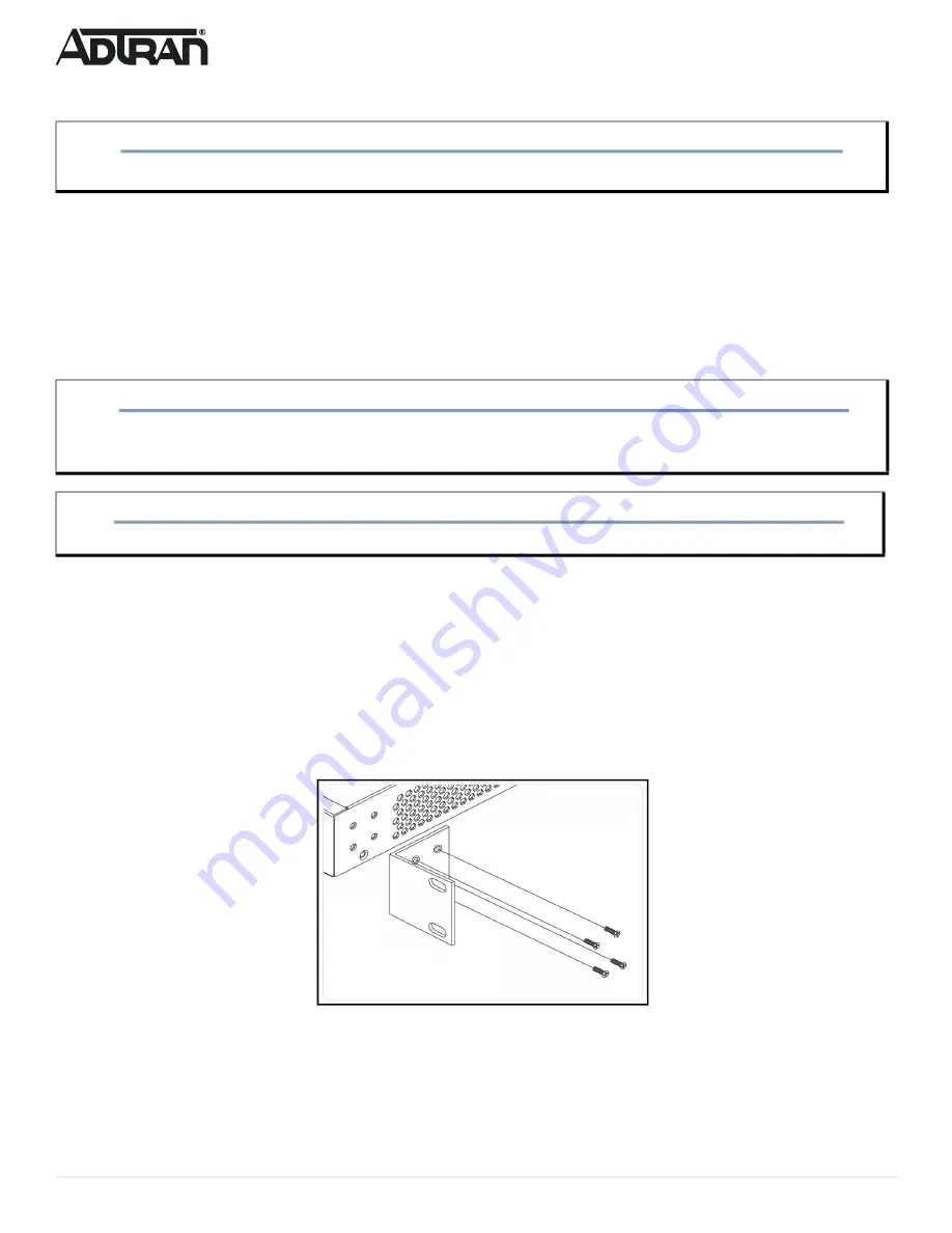
1. Attach the brackets provided in the mounting kit to both sides of the chassis. Insert the provided screws and tighten them with a screwdriver to 

secure the brackets.

Figure 3. Attaching Brackets to the Switch

2. Position the chassis in the stationary equipment rack. Allow 1-inch of clearance between units.

NOTE

g

Refer to the national, state and local electrical codes for the requirements for power, grounding, wiring, and installation methods. 

CAUTION!

f

The NetVanta 1560-24 is intended for indoor use only. Ethernet, PoE cables and attached equipment are intended for use within the same 

building with equipotential bonding, and not intended to be placed in separate buildings or structures. Failure to deploy as described could 

result in permanent damage from lightning or other electrical events and voids the warranty.

WARNING!

f

This equipment is not suitable for use in locations where children are likely to be present.

Summary of Contents for 17101564F1

Page 1: ...efore installing or servicing this equipment NetVanta 1560 24 SYSTEM CONSOLE USB RESET 1 2 3 4 5 6 7 8 9 10 11 12 13 14 15 16 17 18 19 20 21 22 23 24 25 26 SYS LED CONSOLE Port 10 100 1000 2500 RJ 45...

Page 2: ...them with a screwdriver to secure the brackets Figure 3 Attaching Brackets to the Switch 2 Position the chassis in the stationary equipment rack Allow 1 inch of clearance between units NOTE g Refer t...

Page 3: ...a template install four 8 PAN head screws 0 75 inch using two for each bracket as shown in Figure 6 in the appropriate location on the wall Be aware of the dimensional limitations of the screws 2 Slid...

Page 4: ...equipment and must be easily accessible 3 Confirm that the power is connected properly The SYSTEM LED should be ON see SYSTEM Status LED Figure 7 Connecting the AC Power Cord CAUTION f The NetVanta 15...

Page 5: ...AC Surge Protection Device be installed at the AC input connection to the local AC Powered product The Surge Protection device should provide L N L G and N G protection It is also recommended that th...

Page 6: ...IP address 3 Power up the switch to be initially configured and wait until it has finished its start up processes 4 Connect the PC to any port on the switch using a standard Ethernet cable and check t...

Page 7: ...atus LEDs The Port Status LEDs indicate the current status of each port NOTE g There are many terminal emulation applications available on the web PuTTY SecureCRT and HyperTerminal are a few examples...

Page 8: ...tore to Factory Defaults 7 12 seconds Flashing Green All LEDs are ON Symptoms Possible Causes Suggested Solutions System LED is OFF The switch is not receiving power 1 Check if correct power cord is c...

Page 9: ...g or maintaining always place devices on an approved antistatic mat that is electrically grounded Warranty ADTRAN will replace or repair this product within the warranty period if it does not meet its...

Reviews: