Power Connections
61181001L1-5E
9
Power Connection
NOTE
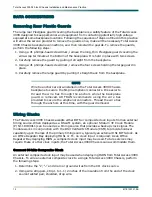
Connect to a reliably grounded –48 VDC source that is electrically
isolated from the AC source.
NOTE
A readily accessible disconnect device, such as a rack mount fuse
and alarm panel that is suitably approved and rated, should be
incorporated in the fixed wiring.
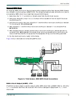
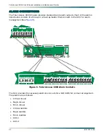
Dual power buses are provided with separate battery returns. Power connections use two
separate opposing blocks, labeled
TS1
and
TS2
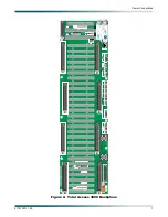
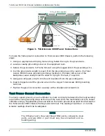
, located on the lower left side of the backplane
below the Pair 5 amphenol connector (see
). The terminals are on 0.4375 inch centers
and allow for wire gauges up to 10 AWG. There is a separate Frame Ground terminal, labeled
FR GND
, located on the bottom left side of the backplane, and can accommodate up to 8 AWG
wire. The two power inputs,
TS1
and
TS2
, are identical in function and can be used for
redundant power configurations. The Frame Ground terminal routes to mechanical contact
points and provides an electrical connection to the chassis metalwork. The two power buses
and Frame Ground route to all the cards in the chassis. Plug-in cards are responsible for any
necessary DC-DC conversion.
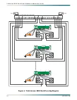
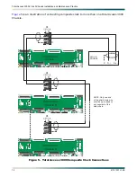
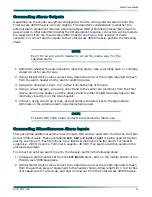
depicts how the Total Access 3000 Chassis can be powered from a typical dual-feed
fuse and alarm panel. Seven shelves are depicted. The number of shelves that can be placed in
a 7-foot central office rack depends on the type of service deployed, the number of access
modules in the chassis, and, in the case of HDSL or T1, the number of repeaters being
powered.
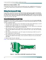
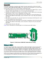
After connecting and checking the ground to the Total Access 3000 Chassis, connect power to
the chassis. Check to make sure the power source is providing the correct power and polarity
to the chassis. To connect power to the chassis, perform the following steps:
1. Determine which fuse pairs are to supply power to the Total Access 3000 chassis.
2. Remove the fuses from the
A
and
B
slots for the pair determined in the above.
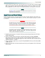
3. Using a #1 phillips-head screwdriver, remove the Plexiglass cover to the power terminals,
labeled
TS1
and
TS2
.
4. Cut four lengths of AWG 10 wire to reach from the terminals on the fuse and alarm panel
to the power terminals on the Total Access 3000 Chassis. Be sure to include enough
length to allow for tying the wire neatly to the frame as specified by CO SOP.
5. Using the crimping tool, connect an appropriate lug to each end of the wires.
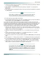
6. Using a screwdriver appropriate for the fuse and alarm panel terminals, and a straight
slot screwdriver for the Total Access 3000 Chassis power terminal, connect the ends of
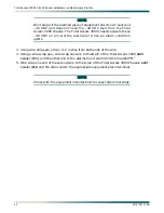
one wire between the “A” CO –48 VDC supply and the
–48 VDC –48 PRI
terminal on the Total
Access 3000 backplane. Secure the wire to the backplane with wire tie through the tie
anchor.

