LEC-
iMX8M plus User’s Guide 1.0
SGET SMARC Rev 2.1
Page 38
copyright © 2021 ADLINK Technology Inc.
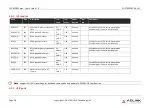
4.3.12
ESPI
Name
Pin
#
Description
I/O
Type
I/O
Level
Power
Domain
PU /
PD
Comments
ESPI_CS0#
P54
ESPI1 Master Chip Select 0
O
CMOS
1.8V
Standby
ESPI_CS1#
P55
ESPI1 Master Chip Select 1
O
CMOS
1.8V
Standby
ESPI_CK
P56
ESPI Master Clock output
O
CMOS
1.8V
Standby
ESPI_RESET#
S58
ESPI Reset
O
CMOS
1.8V
Standby
Reset the eSPI interface for both master and slaves.
eSPI Reset# is typically driven from eSPI master to eSPI slaves
ESPI_ALERT0#
ESPI_ALERT1#
S43
S44
ESPI ALERT
I OD
CMOS
1.8V
Standby
This pin is used by eSPI slave to request service from eSPI.master.Alert# is
an open-drain output from the slave.
This pin is optional for Single Master-Single Slave configuration where
I/O[1] can be used to signal the Alert event.
ESPI_IO_0
ESPI_IO_1
ESPI_IO_2
ESPI_IO_3
P58
P57
S56
S57
ESPI Master Data Input /
Output.
I/O
CMOS
1.8V
Standby
ESPI_IO_0 can also be used as SPI1_DO (MOSI)
ESPI_IO_1 can also be used as SPI1_DIN (MISO)
In Single I/O mode, ESPI_IO_0 is the eSPI master output / eSPI slave input
(MOSI) whereas ESPI_IO_1 is the SPI master input / eSPI slave output
(MISO).
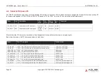
Note
: On NXP i.MX8M plus parts SPI is used
Summary of Contents for SMARC NXP i.MX8M-plus Quad NPU
Page 1: ...LEC IMX8MP 02 01 2021...


