12
Introduction
Leading
EDGE COMPUTING
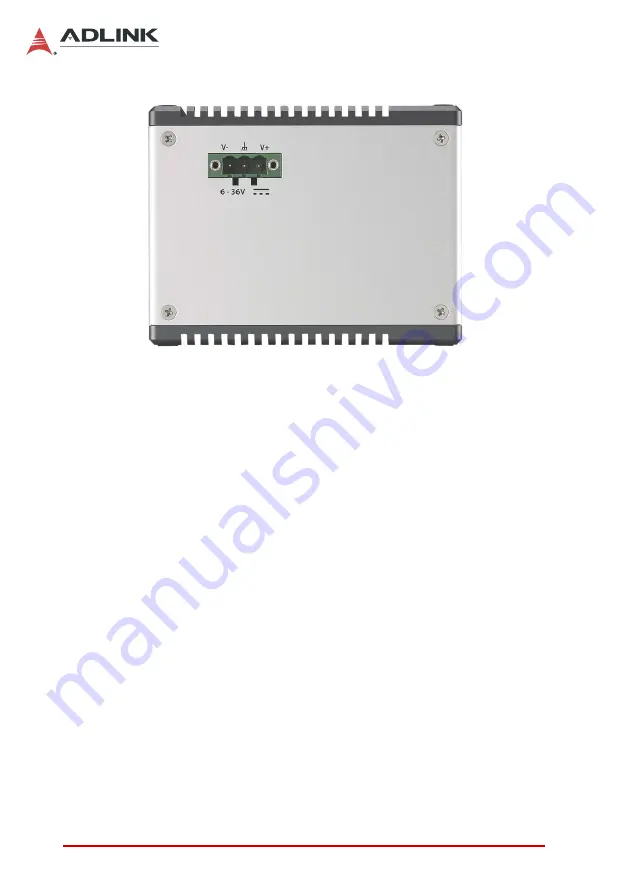
Figure 1-9: Left Side Panel I/O
Power button
Reset button
Antenna port
DisplayPort connector
LED operation indicators (x3)
LED user-defined indicators (x3)
DB-9P COM ports (x2)
GbE ports (x2)
USB2.0 ports (x2)
USB3.0 ports (x2)
BNC (x4)
4-pin GPI/O w/ DGND
DC power supply connector
1.4.1
Power Button
A non-latched push button with blue LED indicator. System is
turned on when pressed, and the power LED lit. If the system
hangs, depressing the button for 5 seconds powers down the sys-
tem.
Summary of Contents for MCM-100
Page 6: ...vi Preface Leading EDGE COMPUTING This page intentionally left blank...
Page 14: ...xiv List of Tables Leading EDGE COMPUTING This page intentionally left blank...
Page 16: ...xvi List of Figures Leading EDGE COMPUTING This page intentionally left blank...
Page 34: ...18 Introduction Leading EDGE COMPUTING This page intentionally left blank...
Page 37: ...Getting Started 21 MCM 100 102 161 58 150 38 134 3 118 22 113 95 60 6...
Page 44: ...28 Getting Started Leading EDGE COMPUTING This page intentionally left blank...
Page 50: ...34 Driver Application Installation Leading EDGE COMPUTING This page intentionally left blank...
Page 64: ...48 Operation Leading EDGE COMPUTING This page intentionally left blank...
Page 87: ...BIOS Setup 71 MCM 100 102 SEMA Features Shows features supported by the SEMA version...
Page 90: ...74 BIOS Setup Leading EDGE COMPUTING Flags Shows BMC flags with exception codes...
Page 91: ...BIOS Setup 75 MCM 100 102 Power Up Lists Power Up Watchdog status...
Page 100: ...84 BIOS Setup Leading EDGE COMPUTING This page intentionally left blank...
Page 116: ...100 Important Safety Instructions Leading EDGE COMPUTING This page intentionally left blank...


