LEC-
iMX6R2 User’s Guide
SGET SMARC Rev 2.1
Page 39
copyright © 2021 ADLINK Technology Inc.
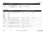
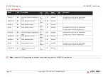
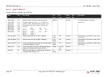
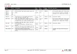
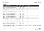
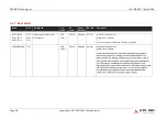
4.3.9
SDIO
Name
Pin #
Description
I/O
Type
I/O
Level
Power
Domain
PU / PD Comments
SDIO_D0
SDIO_D1
SDIO_D2
SDIO_D3
P39
P40
P41
P42
SDIO Data lines. These signals operate in push-pull
mode.
I/O
CMOS
1.8V or
3.3V
Runtime
SDIO controller will detect SD Cards voltage
level (1.8V for UHS-I and 3.3V for standard)
and adjust its I/O voltage level accordingly
SDIO_WP
P33
SDIO Write Protect. This signal denotes the state
of the write-protect tab on SD cards.
I OD
CMOS
3.3V
Runtime PU 10k
Pulled up on module
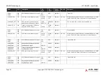
SDIO_CMD
P34
SDIO Command/Response. This signal is used for
card initialization and for command transfers. During
initialization mode this signal is open drain. During
command transfer this signal is in push-pull mode.
I/O
CMOS
1.8V or
3.3V
Runtime
SDIO controller will detect SD Cards voltage
level (1.8V for UHS-I and 3.3V for standard)
and adjust its I/O voltage level accordingly
SDIO_CD#
P35
SDIO Card Detect.
This signal indicates when a SDIO/MMC card is
present.
I OD
CMOS
3.3V
Runtime PU 10k
Pulled up on module
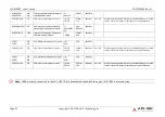
SDIO_CK
P36
SDIO Clock. With each cycle of this signal a one-bit
transfer on the command and each data line occurs.
O
CMOS
1.8V or
3.3V
Runtime
SDIO_PWR_EN P37
SDIO Power Enable. This signal is used to
enable the power being supplied to a SD/MMC card
device.
O
CMOS
3.3V
Runtime
should be driven low in STB Mode by the
module

