


Installation
17
2.7 PCI-7250 and PCI-7251 Connection
There are 8-relay outputs and 8-isolation inputs on both the PCI-
7250 and PCI-7251. The PCI-7251 is used as an expansion for
the PCI-7250. The operations of the PCI-7251 are the same as
that of the PCI-7250. There can be at most 3 PCI-7251 expansion
boards to one PCI-7250. Therefore, the PCI-7250 can control up
to 32 relays and detect 32 input signals.
Figure 2-4: Connection between PCI-7250 and PCI-7251
Legend
Din:
Digital input channel n
IGND:
Ground of DIn signals
DinH:
Digital input channel n with positive polarity
DinL:
Digital input channel n with negative polarity
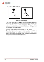
NC n:
Normal close pin of relay n
NO n:
Normal open pin of relay n
COM n:
Common pin of relay n
Summary of Contents for cPCI-7252
Page 4: ......
Page 10: ......
Page 18: ...8 Introduction ...
Page 20: ...10 Installation 2 2 PCB Layout PCI 7250 PCB Layout Figure 2 1 PCI 7250 Layout ...
Page 21: ...Installation 11 cPCI 7252 PCB Layout Figure 2 2 cPCI 7252 Layout ...
Page 28: ...18 Installation ...
Page 32: ...22 Registers ...
Page 43: ...C C Libraries 33 Return Code ERR_NoError ERR_BoardNoInit ...
Page 48: ...38 C C Libraries ...
Page 52: ...42 Appendix ...


