


www.adeept.com
65
How Should I Use Arduino?
If you are a beginner with Arduino, Arduino learning kits on our website
would
be a prefect step into this fantastic field!
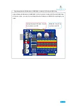
Two types of Arduino board are used in this car kit: Adeept UNO R3 board and Arduino Nano
board.
Power
The Arduino/Genuino Uno board can be powered via the USB connection or with an external
power supply. The power source is selected automatically.
External (non-USB) power can come either from an AC-to-DC adapter (wall-wart) or battery. The
adapter can be connected by plugging a 2.1mm center-positive plug into the board's power jack.
Leads from a battery can be inserted in the GND and Vin pin headers of the POWER connector.
The board can operate on an external supply from 6 to 20 volts. If supplied with less than 7V,
however, the 5V pin may supply less than five volts and the board may become unstable. If using
more than 12V, the voltage regulator may overheat and damage the board. The recommended
range is 7 to 12 volts.
The power pins are as follows:
Vin. The input voltage to the Arduino/Genuino board when it's using an external power source
(as opposed to 5 volts from the USB connection or other regulated power source). You can supply
voltage through this pin, or, if supplying voltage via the power jack, access it through this pin.
5V. This pin outputs a regulated 5V from the regulator on the board. The board can be supplied
with power either from the DC power jack (7 - 12V), the USB connector (5V), or the VIN pin of the
board (7-12V). Supplying voltage via the 5V or 3.3V pins bypasses the regulator, and can damage
your board, which is not recommended.
3V3. A 3.3 volt supply generated by the on-board regulator. Maximum current draw is 50 mA.
GND. Ground pins.
IOREF. This pin on the Arduino/Genuino board provides the voltage reference with which the
microcontroller operates. A properly configured shield can read the IOREF pin voltage and select
the appropriate power source or enable voltage translators on the outputs to work with the 5V
or 3.3V.
Summary of Contents for Hexapod 6 Legs Spider Robot
Page 1: ...www adeept com 1...
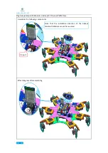
Page 40: ...www adeept com 36 The effect diagram after the assembly of three right feet...
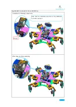
Page 49: ...www adeept com 45 The effect diagram after the assembly of three left feet...
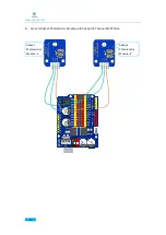
Page 63: ...www adeept com 59 C Connect Adeept Ultrasonic Module with Adeept 32 Channel PWM Drive...
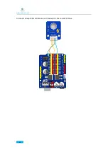
Page 64: ...www adeept com 60 D Connect Adeept RGB LED Module with Adeept 32 Channel PWM Drive...
Page 65: ...www adeept com 61 E Connect Adeept Passive Buzzer Module with Adeept 32 Channel PWM Drive...
Page 66: ...www adeept com 62 F Connect 18650x2 Battery Holder with Adeept 32 Channel PWM Drive...
Page 67: ...www adeept com 63 G Connect 18650x2 Battery Holder with Adeept Remote Control Shield...
Page 75: ...www adeept com 71...
Page 77: ...www adeept com 73...
Page 79: ...www adeept com 75 Click the button to upload the sketch to the board...
Page 83: ...www adeept com 79...


