background image

10

INST

ALLA

TION

CONFIGURA

TION

OPERA

TION

FUR

THER

INFORMA

TION

INDEX

Remote control connection

The RCU port allows the switch unit to be connected 
to, and controlled by an external source. Refer to the 

API 

Manual (MAN-000022)

 for programming detail.

Power connection

IMPORTANT: Ensure that the video displays connected to the secure switch are 

powered on before applying power to the secure switch itself. 
The supplied power adapter uses a locking-type plug to help prevent accidental 

disconnection from the secure switch; please follow the instructions below when 

disconnecting the power adapter.   

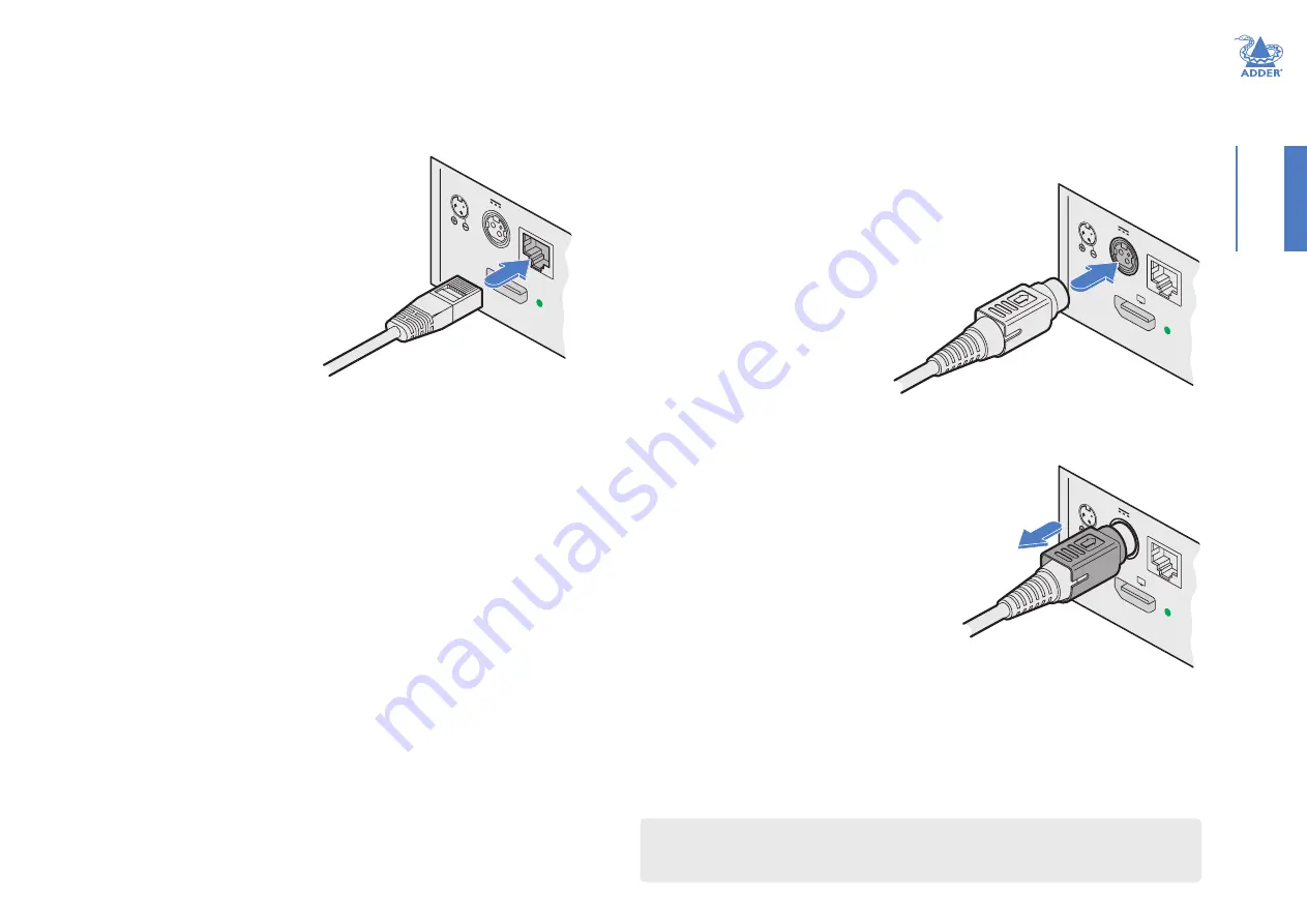
To connect the power adapter

Attach the output plug of the supplied power adapter

 to 

the power input socket on the left side of the rear panel. 

As you insert the plug, pull back slightly on the outer 
body to assist the locking mechanism until the plug is fully 

inserted.

Attach the appropriate country-specific plug to the power adapter body and insert it 

into a nearby mains outlet.

To disconnect the power adapter

1  Isolate the power adapter from the mains 

supply.

2  Grasp the outer body of the power adapter 

plug where it connects with the node.

Gently pull the body of the outer plug away 
from the node. As the body of the plug slides 

back, it will release from the socket and you 

can fully withdraw the whole plug. 

IMPORTANT: Please read and adhere to the electrical safety information 

given within the supplied safety guide. In particular, do not use an unearthed 

power socket or extension cable.

To connect a remote control source

Insert the plug from the remote control source 

cable into the RCU socket on left side of the rear 
panel. 

From the  

power adapter

RCU

CON

SOLE

2

12V

2.5A

From the  

remote control 

source

RCU

CON

SOLE

2

12V

2.5A

Gently pull back the 

plug outer body to 

release the lock 

RCU

CON

SOLE

2

12V

2.5

A

Once powered up, the Console ‘in use’ indicators will flash for a few seconds whilst the 

peripheral information is read. Once the peripheral has been accepted, the indicator 
will remain on. A security feature means that peripheral information will not be re-read 

unless the switch is power cycled. This is designed to prevent peripherals being replaced.
The power up sequence takes about 30 seconds for the switch to become operational.

Note: When the switch is under remote control, the front panel indicators will continue to reflect 

the current selected channel, however, the buttons will have no effect.
A security feature means that once the switch is under remote control, it will remain so until the 

unit is power cycled, regardless of whether the remote control cable is disconnected.

Summary of Contents for ADDERView Secure AVS-1124

Page 1: ...ADDERView Secure AVS 1124 User Guide Experts in Connectivity Solutions KVM Switching Solutions...

Page 2: ...tial display setup 11 General configuration 11 Using with dual head computers 11 Using the OSD 12 Channel names and security levels 12 Video Settings 13 Channel Settings 14 USB Settings 15 Advanced Op...

Page 3: ...Clear channel identification to reduce the chances of operator error by displaying a user defined name and security classification for each channel on the status display The color of the channel indic...

Page 4: ...bels to provide visual indications in case of an enclosure intrusion attempt When opening product packaging inspect the tampering evident labels If for any reason one or more tamper evident label is m...

Page 5: ...mpliant with Microsoft Digitizer Computer connections 4x DVI D 4x USB type B 4x Audio 3 5mm Console connections 2x HDMI 2x USB type A Audio 3 5mm RJ12 options port Front panel Audio hold button and st...

Page 6: ...CONFIGURATION OPERATION FURTHER INFORMATION INDEX SUPPLIED ITEMS Information wallet containing Four self adhesive rubber feet Quick start guide Safety document AVS 1124 unit Power adapter with univer...

Page 7: ...Audio cable 2m 3 5mm stereo jacks Part number VSC22 USB cable 2m type A to B Part number VSC24 S E C U R E 4 port smart card reader Part number AS 4CR Single link DVI D to DVI D video cable 2m Part nu...

Page 8: ...before applying power RCU 1 1 2 2 3 4 CONSOLE 12V 2 5A Primary console HDMI display Power in Computer DVI video connection Speakers Keyboard and mouse Computer USB link Computer audio link Computer p...

Page 9: ...60Hz To make connections to each computer port 1 Attach a cable between the DVI video connector and the primary video output connector on the computer 2 Insert one of the supplied USB type A to type...

Page 10: ...deo display to the HDMI connector marked 1 2 Where a secondary video display is also to be used repeat step 1 for the HDMI connector marked 2 3 Connect the USB leads from the console mouse and keyboar...

Page 11: ...ode As the body of the plug slides back it will release from the socket and you can fully withdraw the whole plug IMPORTANT Please read and adhere to the electrical safety information given within the...

Page 12: ...names and security levels front panel button colors etc USB Settings including mouse configuration and hotkey choice Advanced Operation including factory reset To access the OSD menu type L Ctrl R Ctr...

Page 13: ...changes are actioned as soon as you click an option To exit the OSD 1 Click the X in the top right corner or press the Esc key OSD pages The OSD options are separated into four distinct pages Video S...

Page 14: ...PCs rather than the default single head PCs The default None setting means that the input channels are treated as single head but the channels 1 2 and 3 4 may be designated as dual heads Please refer...

Page 15: ...is unpinned which means it may be located on top or behind other windows as they are moved across the display Alternatively the window may be pinned to the top or sent to the back Channel Color On the...

Page 16: ...icated to the host PC Notes Consumer Report is a type of keyboard Mac host PCs aren t supported Some versions of Linux don t support Absolute mouse Keyboard Hotkeys Determines whether keyboard hotkeys...

Page 17: ...lower case accepted 2 Click the Advanced Operation menu item OSD Advanced Operation Reset to Factory Defaults Removes all user entered configuration details This operation cannot be undone Note To av...

Page 18: ...then o upper or lower case accepted 2 Click the System Information menu item OSD System Information This page is intended to aid technical support It displays the version number for the System andVid...

Page 19: ...ltaneously either on a single display or dual displays Keyboard and mouse control is assigned to a single host computer at a time and is switchable using a number of methods see page 19 Channel button...

Page 20: ...This allows you to perform certain tasks such as resizing windows and arranging preset layouts It is quick and easy to change between the two modes as follows Entering and exiting system mode To enter...

Page 21: ...lay To use autoscaling The autoscaling feature allows selected windows to fill the screen either respecting or overriding the aspect ratio depending on the selected option Autoscaling can be enabled e...

Page 22: ...information including the following Getting assistance see right Appendix A Hotkey commands GETTING ASSISTANCE If you are still experiencing problems after checking the information contained within t...

Page 23: ...2 2560 x 1440 3 2560 x 1600 4 1920 x 1080 5 1920 x 1200 6 3840 x 1080 7 3440 x 1440 8 3840 x 2160 Unpin all windows F11 f r Pin unpin window toggle F11 F where is the required function key F1 to F8 Pi...

Page 24: ...3 INSTALLATION CONFIGURATION OPERATION FURTHER INFORMATION INDEX www ctxd com Documentation by 2021 Adder Technology Limited All trademarks are acknowledged Part No MAN 000007 Release 1 0 www adder co...

Page 25: ...te control unit 10 D Displays initial setup 11 F Focus layout 18 H Hotkeys 22 L Labels tamper evident 3 O On Screen Display OSD 12 P Ports 7 Power in 10 Preset layouts 20 Q Quadrant See Tile layout S...

Reviews: