21
CONFIGURA
TION
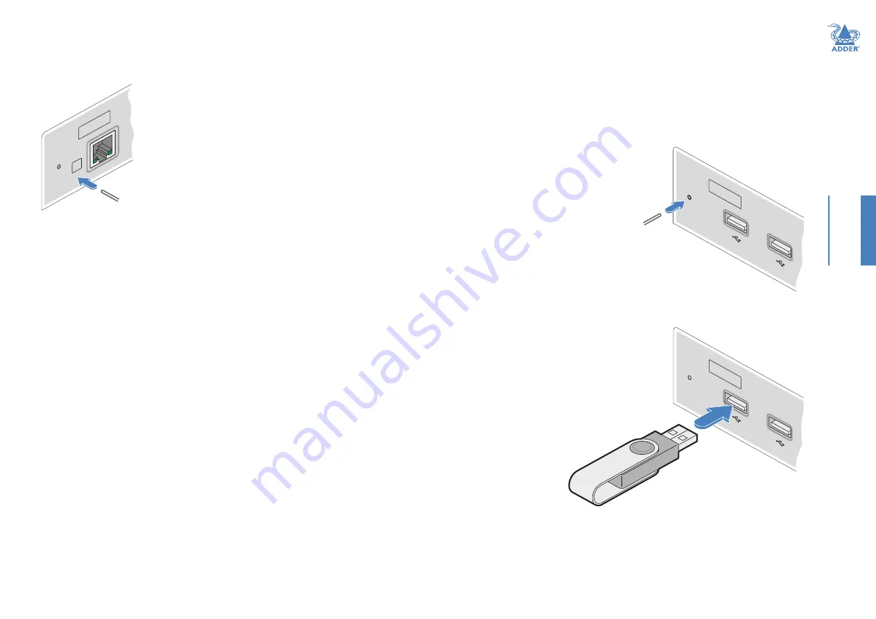
RESETTING A MODULE
On the left side of the front panel of each module, you will find a small reset hole which
is used to invoke special functions.
AD
DE
RL
ink
™
XD
6 1
2
LIN
K
A
UPGRADING FIRMWARE
Firmware upgrades are periodically made available for products via the Adder website
(www.adder.com). Use this procedure to upgrade the firmware in both ADDERLink XD
extenders.
Note: XD612 upgrades require roughly 6 minutes to complete; XD614 upgrades require roughly
11 minutes.
To upgrade the firmware
1
Download the appropriate firmware upgrade
file from the
Downloads
section of the
ADDERLink XD product page within the
Adder website. Copy the upgrade file to an
empty (but FAT32-formatted) USB memory
stick.
2 Ensure that the transmitter and receiver are
linked and powered on. Also check that there
are no USB drives inserted in the receiver
module’s ports.
3
On the receiver, press and hold a thin
implement, such as a straightened paperclip,
in the reset hole until the receiver’s STS
indicator flashes red/blue. The receiver is
now in upgrade mode.
4 Wait for the STS indicator
link to turn green, signifying
that the link is established.
5 Insert the memory stick
containing the upgrade file
into the front panel left USB
port.
The upgrade should begin
and both units will flash
their STS indicators red/
green to show the upgrade
process is in progress.
Following a successful
upgrade, both units will
automatically reboot and
run the new firmware.
6 Display the Dashboard (see page 20
) to view the upgrade progress. The Status field
will display a message if an error occurs. In an error situation, it may be necessary to
reboot the modules to use the existing firmware version.
AD
DE
RLin
k
™
XD
6 1
2
USB memory
stick with
upgrade file
AD
DE
RLin
k
™
XD
6 1
2
Press and hold
the recessed
reset button
To reset a module
1
Use a thin implement, such as a straightened
paperclip to press and release the button
concealed behind the small hole. The PWR
indicator will show
red
.
After a few seconds, the indicator will
change from
red
to
green
to show that the
reset procedure is complete.


