16
INST
ALLA
TION
Fiber optic link
Each pair of AdderLink XD modules require optional SFP+ fiber optic modules of your
choice (single or multi-mode). The fiber optic cable used must match the SFP+ type and
also be of a suitable type for the distance being covered. See
for
details.
To make the fiber optic link
IMPORTANT: Ensure the power supply is off/disconnected before inserting or removing
an SFP+ module.
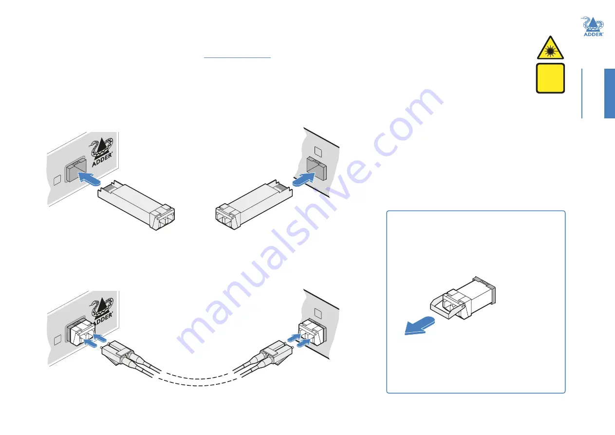
1 Remove an SFP+ module from its protective packing and insert it fully into the empty
slot on the AdderLink XD module. The XD transmitter slot is located on the front
panel; the XD receiver slot is situated on the rear panel:
2 Repeat for the other SFP+ module on the other module.
3
For each SFP+ module, remove the black rubber insert that protects the sensors.
4
If fitted, remove the dual inserts that protect the fiber optic connectors.
5
Insert the fiber optic connectors into the SFP+ module so that they click into place:
6 Repeat steps 4 and 5 at the other end.
LIN
K
B
T X
TRA
NSM
IT
DC
LINK
B
Transmitter
front panel
Receiver
rear panel
To remove an SFP+ module
1
If fitted, remove the dual fiber optic connectors from
the SFP+ module (press in the release tab of the fiber
optic connectors to disengage them).
2 Unclip the small extraction lever and open it out (this
action releases a locking tab and also provides a grip
point).
3 Gently pull on the extraction lever to withdraw the
SFP+ module from the slot.
4
If the SFP+ module and/or fiber optic connector will
remain unused for any period of time, be sure to fit the
protective inserts to keep the optical interfaces clean.
Note: In order to maintain a high level of confidence in the fiber
optic link, it is recommended that Adder supplied SFPs are used:
(SFP+-MM-LC-10G or SFP+-SM-LC-10G).
If alternative parts are used, the system will detect this and will
flash the front panel LNK indicator.
Transmitter
front panel
Receiver
rear panel
DC
LINK
B
LIN
K
B
T X
TRA
NSM
IT
WARNING
CLASS 1
laser
product


