4601 I-V Meter Operation Manual
5.9.2 Operational Principles
5-53
5.9.2.2
ADC3 Measurement Circuit
•
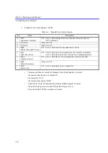
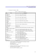
The ADC3 measurement circuit can switch between eight functions: Ir, Em, Tc1, Pt1, Ad1, Tc2, Pt2
and Ad2 in the DC source mode or spot measurement.
In the sweep source mode, only Ir is selected and measured simultaneously with Vm and Im.
•
The reference cell current measurement circuit (Ir) is a 0 V source current measurement circuit.
This circuit is 4-terminal output and operates to make both ends of the reference cell 0 V by the volt-
age sense terE and -E.
Current measurement is performed by measuring the voltage across the sense resistor Rs in the output
circuit.
The range is switched between 3 mA, 30 mA and 300 mA by switching this sense resistor.
The output amplifier A10 can output up to approximately 340 mA at the positive side (sink), however
it can output up to approximately -34 mA at the negative side (source).
•
The external voltage measurement circuit (Em) switches the range between 30 mV, 300 mV and 3 V
by switching the gain of the high input impedance amplifier A12 between x100, x10 and x1.
•
The thermocouple measurement circuit (Tc1) measures the temperature of thermocouples by com-
paring the output voltage from the thermocouple sensor and the reference junction voltage.
•
The Pt measurement circuit (Pt1) performs 4-terminal resistance measurement by applying current
of 1 mA between pin 1 and pin 4 of the terminal from the constant current source and measures the
voltages of pin 2 and pin 3 alternately.
•
The Ad measurement circuit (Ad1) measures temperature by connecting the IC temperature sensor
AD590 to pin 2 and pin 3 of the terminal. Power is supplied from +5 V, the output current from the
sensor is applied to 1 k
, and current is measured, making it possible to measure temperature.
•
Pt1 and Ad1 use the same measurement terminal. Either one is used by setting Pt/Ad Select.
•
The circuits of Tc2, Pt2 and Ad2 are the same as those of Tc1, Pt1 and Ad1 respectively.


