


4.5.5 Check connection
To check the connection, connect from a place where the remote control connection already works.
1. Remove the multiwire cable. See §
.
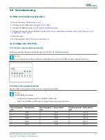
2. Set the rotary switch SW3 (A) of the LMC PCB to position 9. Now the equipment cabinet is remote controlled.
3. Check all remote control functions.
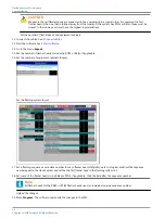
4. Open the configuration software tool in menu IO .
5. Simulate an error.
6. Check if the remote control receives the signals.
4.6 Commissioning records
4.6.1 Use tables
Use the tables to record all the necessary information in the commissioning phase.
4.6.2 Commissioning record tables
Table 5: Commissioning record tables - general
Approach
Mode name
Cycle time in seconds
Table 6: Commissioning record tables - flasher head 1 to 11
Flasher head
1
2
3
4
5
6
7
8
9
10
11
Equipment cabinet
SW2 address
REIL/RTIL
FCU-3 / FCU-1
FCU-1 phase
connect
Termination
resistance set
P1/P3 to
P1/P3 to
Timing [ms]
Group
UM-4019_AM02-620e, Rev. 3.0, 2020/05/12
29
Copyright
©
ADB Safegate, All Rights Reserved
Summary of Contents for FCU-1-in-1
Page 2: ......
Page 8: ...Flashing System Maintenance TABLE OF CONTENTS viii Copyright ADB Safegate All Rights Reserved ...
Page 18: ...Flashing System Maintenance Safety 8 Copyright ADB Safegate All Rights Reserved ...
Page 28: ...Flashing System Maintenance Introduction 18 Copyright ADB Safegate All Rights Reserved ...
Page 42: ...Flashing System Maintenance Commissioning 32 Copyright ADB Safegate All Rights Reserved ...
Page 64: ...Flashing System Maintenance Maintenance 54 Copyright ADB Safegate All Rights Reserved ...
Page 106: ...Flashing System Maintenance Technical data 96 Copyright ADB Safegate All Rights Reserved ...
Page 110: ......