i
Acute Technology Inc.
Copyright
2016
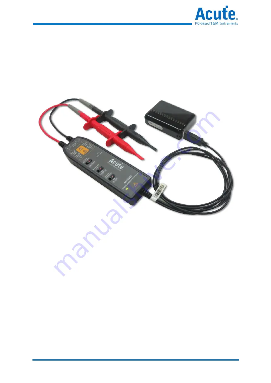
High Voltage Differential Probe user's manual
ADP1025
25MHz/700Vpk
ADP2025
25MHz/1400Vpk
Page 1: ...i Acute Technology Inc Copyright 2016 High Voltage Differential Probe user s manual ADP1025 25MHz 700Vpk ADP2025 25MHz 1400Vpk...
Page 2: ...10 S Sp pe ec ci if fi ic ca at ti io on ns s 1 12 2 O Op pe er ra at ti io on n 1 13 3 Connecting the probe to the instrument with input impedance of 1 M 13 Connecting the probe to the test circuit...
Page 3: ...his probe ensure that the output BNC connector is attached to the BNC connector of the measurement instrument while the measurement instrument is properly grounded Observe all terminal ratings To avoi...
Page 4: ...under test Disconnect the probe input leads from the circuit under test before disconnecting the probe from the measurement instrument Do not operate in wet damp conditions Do not operate in an explos...
Page 5: ...ry hazard immediately accessible as you read the marking Danger statements identify conditions or practices that could result in injury or loss of life WARNING indicates an injury hazard not immediate...
Page 6: ...d and conducted emissions Group 1 Class B IEC 61000 4 2 2008 Electrostatic discharge immunity ESD IEC 61000 4 3 2008 RF electromagnetic field immunity RS IEC 61000 4 4 2012 Electrical fast transient b...
Page 7: ...ted in clean rooms Pollution Degree 2 Normally only dry nonconductive pollution occurs Occasionally a temporary conductivity that is caused by condensation must be expected This location is a typical...
Page 8: ...e installation Measurement Category III For measurements performed in the building installation Measurement Category II For measurements performed on circuits directly connected to the low voltage ins...
Page 9: ...nd easily on any ground referenced oscilloscope WARNING For safe operation do not use the ADP High voltage Differential Probe with oscilloscopes that have floating inputs isolated inputs The ADP High...
Page 10: ...shock or fire do not exceed either the voltage rating or category rating of the probe or the probe accessory whichever is the lesser of the two WARNING For safe operation do not use the ADP High volt...
Page 11: ...probe bandwidth below 5 MHz 5 MHz is close to the switching frequency of most switching transistors FETs in switch mode power supplies SMPS The 5MHz filter assists in the characterization and testing...
Page 12: ...of the probes by 67 in 1 5 m The banana ends connect to all of the clip accessories that are included with the probes One pair of extender leads are included with the probes Maximum ratings 2300 V CA...
Page 13: ...iver with Slot end is for opening Offset cover and with Frierson end is for adjusting trimmer WARNING To avoid risk of electric shock or fire do not exceed either the voltage rating or category rating...
Page 14: ...0V CAT III Impulse withstand 2500V 4000V CMRR typical DC 80dB 100kHz 60dB 1MHz 50dB 10MHz 38dB Output swing 7V to 1Mohm load Offset adjusting range Scope gain 1X Coarse 150mV Coarse 150mV Fine 30mV Ba...
Page 15: ...ights or flashes the output signal may not be accurate Use the 200X setting instead WARNING To avoid electrical shock observe proper safety precautions when working with voltages above 60 VDC or 30 VA...
Page 16: ...s Input leads that form a large loop area will pick up any radiated electromagnetic field that passes through the loop and may induce noise into the probe inputs Because this signal will appear as a d...
Page 17: ...ining DC coupling The offset range of the probe is a function of the oscilloscope s attenuation Some DC offset drift may occur from thermal effects and different power ground loop The probe must have...
Page 18: ...probes 3 Place to the center position of both Fine trimmers 4 If the DC offset of both attenuation path all toward positive or negative position adjust the Coarse trimmer until either one is positive...
Page 19: ...to both input leads of the probe the probe rejects the signal by 80 dB typical and the signal appears as only a 50 mVp p signal on the oscilloscope screen Twisting the Input Leads Twisting the input...
Page 20: ...robe inputs to the AC voltage source 3 Connect the inputs set the voltage range and perform the check as each row of the following table indicates Input 1 Input 2 Mode Range setting Check Hot Ground N...
Page 21: ...cedure can be used to verify the warranted characteristics of the ADP series Active Differential Probes If the product does not meet specifications it should be returned to a Acute service center Ther...
Page 22: ...al Probe Manual Copyright 2016 Acute Technology Inc All Rights Reserved Acute Technology Inc www acute com tw Address 6F 7 12 Ln 609 Sec 5 Chongxin Rd Sanchong Dist New Taipei City 24159 Taiwan Tel 88...