background image

Acuity Brands | One Lithonia Way Conyers, GA 30012 | Phone: 800.535.2465 | www.nlightcontrols.com | © 2020 Acuity Brands Lighting, Inc. | All rights reserved. | Rev. 09/17/2020 


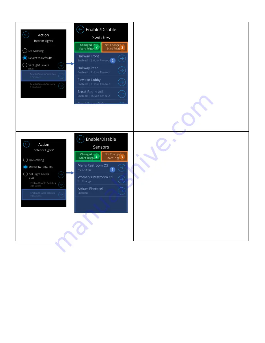
Screen introduces ability to enable, or disable, wall 

switches from being used during execution of the 

schedule. This feature is only accessible when the “Set 

Light Levels” option is selected. 

1.


Switches list – Displays list of switches and their 

current states 

o


No Change – Maintains current switch 

state 

o


Disable – Disables switch from 

performing local broadcast 

o


Enable – Enables switch to perform local 

broadcast 

2.


Change in Start Trigger Tab – Carries all devices 

that were modified by the start trigger 

3.


Not Changed in Start Trigger Tab – Carries all 

devices that were not modified by the start 

trigger 


Screen introduces ability to enable, or disable, sensors 

from adjusting lights during execution of the schedule. 

This feature is only accessible when the “Set Light 

Levels” option is selected. 

1.


Sensors list – Displays list of switches and their 

current states 

o


No Change – Maintains current sensor 

state 

o


Disable – Disables sensor from 

performing local broadcast 

o


Enable – Enables sensor to perform local 

broadcast 

2.


Change in Start Trigger Tab – Carries all devices 

that were modified by the start trigger 

3.


Not Changed in Start Trigger Tab – Carries all 

devices that were not modified by the start 

trigger 


Blink Warning and Timed Override Delay 

Blink warning can be used in schedules that control channels and that are configured such that all controlled channels 

are set to 0% in the End trigger. Timed override delay can be modified by changing the Switch Timeout of switches in the 

Start Trigger. While being adjustable, the timed override delay of blink warning is defaulted at 2 hours. 


NOTE: When enabled, the blink warning triggers lights to blink at the scheduled end time, and lights remain on for 5-

minutes after this time. During this 5-minute window, occupants may extend the lights on time through pressing a 

switch, that is programmed with a "timed override" (configurable from 5 minutes to 12 hours). 

If a switch with 

combination "On/Off" button is utilized, the lights must be turned off and back on to the extended “override” 

duration." For switches with separate "On/Off" buttons, selecting the "On" button will provide this override. 


The following steps must be implemented to effectively configure blink warning: 


Summary of Contents for NLIGHT nDTC

Page 1: ...NLIGHT DIGITAL TIME CLOCK USER MANUAL 2 4...

Page 2: ...Dashboard 10 Suspend Resume Dashboard 11 Suspending Schedules 12 Manually Resuming Schedules 12 Schedule Configuration Dashboard 12 Creating a Normal Schedule 13 Creating a Holiday Schedule 15 Config...

Page 3: ...hting Inc All rights reserved Rev 09 17 2020 Light Control Channel List 28 Hamburger Menu 28 About 29 Settings 29 Screen Behavior 30 Date Time Location 30 Change Access PIN 31 Factory Reset 31 Technic...

Page 4: ...based scheduling on screen programming for small to medium projects requiring minimal footprint and flexibility of configuring Available as a standalone or pre assembled to an ARP panel the device co...

Page 5: ...d nConfig Though the nConfig mobile app can be connected to the nLight network through a nIO BT to allow users the ability to view and program all devices in the network the nDTC is however not discov...

Page 6: ...TC enables the use of user generated holiday to drive periods in which the Holiday Schedules should execute as so known as Custom Holiday events These Custom Holiday Events can run for single days bas...

Page 7: ...an administrator Initial Configuration Users are walked through the initial screens set up the current time and location nDTC device This process is essential as it allows for proper time based execu...

Page 8: ...nly maintains one user level the Administrator Logging in is available through tapping the PIN entry button at the footer of the home dashboard NOTE The administrator PIN is what was PIN initially cre...

Page 9: ...or mode Administrators are also logged out when the unit times out the screen shuts off due to inactivity Dashboard Screens With its ability to create display and modify schedules as well as control l...

Page 10: ...e the time placer events to be run are located under As time passes and events are executed they will transition from the bottom section to the top section Home Dashboard Screen Description The Home D...

Page 11: ...ect from the list of Normal and Holiday schedules the ones they are interested in suspending 1 Normal Holiday Navigation Tab Tab used to transition between the list of Normal and Holiday schedules ava...

Page 12: ...ally Resuming Schedules The workflow below displays how users can override suspended schedules that are set to resume later Figure 7 Workflow to resume suspended schedules Schedule Configuration Dashb...

Page 13: ...All rights reserved Rev 09 17 2020 Figure 8 Normal Schedule Configuration Tab Figure 9 Holiday Schedule Configuration Tab Creating a Normal Schedule Normal Schedules are created in the Normal tab of...

Page 14: ...olds a summary of when and what the End Trigger will be Tapping this section will walk through selecting run time and actions 4 Blink Warning If enabled a blink warning to takes effect at the schedule...

Page 15: ...beled Configuring a Start Trigger for details Configure the End Trigger by setting the end time and actions that will execute during the run Note that configuration of End Triggers is not required Ref...

Page 16: ...ed list of options The flexibility to create Custom Event s is available and will direct you through the workflow of Creating a Custom Event Upon completion of creating the Custom Event the current Ru...

Page 17: ...hting Inc All rights reserved Rev 09 17 2020 The Start time determines when the schedule s Start Trigger will execute Start times can be either set times or astronomical 1 Set Time A defined time base...

Page 18: ...device 2 Channels Tab Used to configure channels to be associated to the Trigger o Navigating out of this tab will result in loss of configuration 3 Outputs Tab Used to configure devices to be associa...

Page 19: ...or state o Disable Disables sensor from performing local broadcast o Enable Enables sensor to perform local broadcast Configuring an End Trigger End Triggers are the actions that run when a schedule i...

Page 20: ...annels or output devices to be controlled by the Trigger 4 Enable Disable Switches Enables or disables wall switches from being used 5 Enable Disable Sensors Enables or disables sensors from being use...

Page 21: ...or from performing local broadcast o Enable Enables sensor to perform local broadcast 2 Change in Start Trigger Tab Carries all devices that were modified by the start trigger 3 Not Changed in Start T...

Page 22: ...for blink warning Timed override delay can be adjusted by changing the Switch Timeout setting of a switch in the Start Trigger The Enable setting must be selected to gain access to modify the Switch T...

Page 23: ...ith blink warning the End Trigger should be scheduled for 5 55 PM Reviewing a Schedule A schedule can be reviewed by tapping on the Next icon at the right of the intended schedule This should direct t...

Page 24: ...licating a Schedule Deleting a Schedule Schedules can be deleted individually by selecting the schedule to be deleted followed by clicking on the trash button Upon confirming the deletion of the sched...

Page 25: ...ber Custom Holiday Events can be found listed in the Runs On screen of a Holiday Schedule and is also visible through the Holidays tab of the Schedule Configuration Dashboard Figure 16 Custom Holiday...

Page 26: ...ents can be created through the Custom Events screen or through Runs On when creating modifying Holiday schedules Enter a name for the Custom Holiday Event and set when the event should be run Reviewi...

Page 27: ...eting a Custom Holiday Event A Custom Holiday Event can be deleted by tapping the Next icon at the right of the intended Custom Event followed by clicking the trash icon in the footer menu Figure 20 D...

Page 28: ...screen enables the control of individual switch channels The control elements are depended on the control type Figure 21 Light Control List Screen Hamburger Menu A hamburger menu Figure 22 is availab...

Page 29: ...e 21 can be accessed through the hamburger menu to display information about the device and points of contact for technical support When contacting technical support it is essential to provide the inf...

Page 30: ...accessed through the settings screen Screen Description The following element blocks allow configuration of the device s screen behavior 1 Color Theme Controls the color theme of the device The optio...

Page 31: ...n screen factory reset through the Settings screen as well as reset through SensorView The on screen factory reset can be triggered using the following workflow Upon selection users will be prompted t...

Page 32: ...g and broadcasting Figure 30 Channels workflow Accessing an individual channel enables view of the channel s settings and allows for modification such as the channel s name Figure 31 Channel Detail Vi...

Page 33: ...evice detail view configuration of the device name broadcasting poles and other device settings can be made Figure 33 Switch Input Device with Photocell settings Outputs On screen configuration of out...

Page 34: ...the nDTC s lighting control zone the nDTC features the ability to display the list of online and offline devices Through this list administrators can opt to remove offline devices from being tracked...

Page 35: ...in the Updates page of the SensorView using the following steps 1 Navigate to the Updates page 2 Select nDTC units to be updated 3 Confirm that the firmware to be updated is greater than what you have...

Reviews: