ABEN16KX User Manual
Page 1 of 36
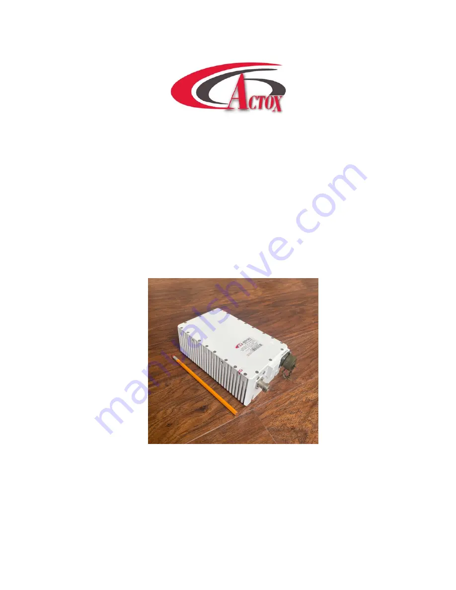
ABEN16KX / ABEN16KXF
16 W (min) Fan-less Extended Ku-Band BUC
USER MANUAL
Page 1: ...ABEN16KX User Manual Page 1 of 36 ABEN16KX ABEN16KXF 16 W min Fan less Extended Ku Band BUC USER MANUAL ...
Page 2: ... description 8 Considerations Securing the Block Up Converter Installing the Block Up Converter 9 LED Indicators Connector Pin Assignment 10Mhz Reference Powering Options Setting L O Setting Tx Rx Frequencies Recommended Test Equipment 13 Technical Specifications 14 Assembly and Installation 15 Connections and Mounting Hardware Functional Overview 16 General IF RF Conversion and Amplification ...
Page 3: ...ntenance 18 Preventive Care Procedure Block Up Converter Cooling System Preventive Maintenance Performance Check Troubleshooting Out of Warranty Repair Appendix 1 Mechanical Drawing 20 Appendix 2 Spare Parts Order Form 21 Appendix 3 M C Commands 22 Appendix 4 M C Connection Instructions 27 ...
Page 4: ...ation and maintenance of the ABEN16KX BUC It contains information intended for engineers technicians and operators working with the block up converter To make inquiries or to report errors of fact or omission in this document please contact Actox Corporation at toll free 866 888 6087 ...
Page 5: ...st and lightest fan less 16W L To Ku Band Block Up Converter and is designed to be mounted on the feed horn The unit is ideal for portable and mobile applications Double L O feature makes unit universal for Ku Band requirements This unit can be powered either with 24 and 48 VDC and consumes less than 92W KEY FEATURES 13 75 14 50 GHz 950 to 1 700 MHz Smallest package size and weight Double L O swit...
Page 6: ...proper packaging please notify Actox Corporation immediately Equipment Damage or Loss Actox Corporation is not responsible for damage or loss of equipment during transit For further information contact the responsible transport carrier When declaring equipment as damaged during transit preserve the original shipping cartons to facilitate inspection reporting Return of Equipment When returning equi...
Page 7: ...r others The block up converter must be installed in accordance with the conditions and recommendations contained in the following sections Safety Precautions Carelessness or mishandling of the block up converter may damage the unit causing serious injury to yourself or others Please adhere to the following WARNING If your unit is equipped with an AC power cord and plug do not tamper with or attem...
Page 8: ...n terminated with a load of VSWR at 2 1 unless otherwise specified All RF specifications shall be met within five minutes after applying power except gain flatness which shall be met after a warm up period of ten minutes During the warm up period the block up converter shall not exhibit any alarm or require an RF mute input signal to reset any alarm fault latches Securing the block up converter Al...
Page 9: ... antenna to the satellite Lightning arrestors should be used at the site to protect personnel and equipment Preparation Mounting Considerations Optional Mounting Brackets are available that will facilitate mounting for most antennas The ODU must be mounted such that Sufficient support is afforded to the BUC the LNB and the Power supply to minimize the effects of antenna sway in strong winds Air mo...
Page 10: ... LED Green All OK SSPA LED Red Summary Alarm L O LED Blinking Yellow L O is set to 12 80GHz L O is set to 13 05GHz NO POWER External 10MHz Reference 10MHz is Absent Internal 10MHz Reference L O LED Yellow NO LED indicators 10MHz LED Green 10MHz LED Red 10MHz LED Green Blinking Connectors Pin Assignment Connector Type Pin Signal Parameter J1 IF IN F type female N A IF Input 0 dBm max 10 MHz Ref IN ...
Page 11: ... TX_P L Ethernet TX_N N GND GND G RS 422 485 TX_B H RS 422 485 TX_A T RS 422 485 RX_B F RS 422 485 RX_A S RS 422 485 232 GND RS_GND G RS 232 TX_RS 232 J RS 232 RX_RS 232 E Control TTL MUTE_IN M To Mute short Pin M Pin V Monitor TTL ALARM_IZ B Summary Fault Alarm TTL Low Monitor Analog 0 to 5V P_OUT_OUT D U 4 5V 0 5V Pmax Monitor Control GND WIRE_GND V ...
Page 12: ...92W 24VDC or 48VDC power supply source Powered via only MS 15 60VDC MS only powered unit uses a 2 pin MS mating connector which is included with the BUC with either a 24VDC or 48VDC external power source with at least 92W Setting the L O Switchable L O is mechanically changed by unscrewing the L O screw and pressing it in with any small object such as toothpick If the BUC is equipped with M C inte...
Page 13: ...th calibrated insertion loss up to 15GHz 40 dB attenuator High Power to match HPA output Assortment of cables connectors and adapters calibrated up to 18 GHz Ensure that the BUC TX output power is disabled to prevent accidental transmission interference with adjacent satellites or transponders before attempting to align or performing any other operation involving the ODU Before attempting any syst...
Page 14: ... stability over temperature range 0 5 dB over 40 MHz 1 8 dB over full band 1 5 dB typ 1 8 dB max Phase noise Exceeds Intelsat s standard IESS308 309 55 dBc Hz max 10 Hz 65 dBc Hz max 100 Hz 75 dBc Hz max 1 KHz 85 dBc Hz max 10 KHz 95 dBc Hz max 100 KHz 115 dBc Hz max 1 MHz Noise power density Transmit Receive 66 dBm Hz max 157 dBm Hz max Noise figure 20 dB max Input V S W R 2 1 max Output V S W R ...
Page 15: ...ried out in dry conditions free of salt spray or excessive humidity This will eliminate the possibility of moisture and other foreign substances from entering the output waveguide flange CAUTION Only authorized technical personnel should perform the Installation and proper electrical hookups of the block up converter The block up converter is designed to operate in an outdoor environment and is wa...
Page 16: ... of the RF Amplifier provide the necessary gain and low insertion loss The amplified signal is transmitted through the output waveguide section to a satellite up link system Monitor and Control optional The block up converter may have a RS 485 and RS 232 serial interface With this option the block up converter can communicate to the indoor unit or redundancy control block up converter via RS 485 o...
Page 17: ...will result in personal injury Safe and careful installation of this block up converter will eliminate the possibility of accidents and provide years of top performance Verify the antenna feed waveguide connection is properly done before the block up converter is energized NOTE The block up converter can withstand any source or load VSWR However the block up converter will meet all specification r...
Page 18: ... Failure to observe this precaution may result in personal injury or death This includes the removal of any RF power originating from other system components When the block up converter is in the hot stand by mode in a redundant system switch it to the operation mode at least once every three months When the block up converter is in the cold stand by mode in a redundant system switch it to the ope...
Page 19: ... From the output power measurements determine rated output power Record value on a test data sheet Measure the Two tone Inter modulation Suppression using two equal signals separated by 5 MHz Record value on test data sheet WARNING Cable connection and disconnection shall be done carefully to avoid physical damage to the cables and connectors which may cause intermittent problems in the future Out...
Page 20: ...ABEN16KX User Manual Page 20 of 36 Appendix 1 Mechanical Drawing ...
Page 21: ... be sent via email to the following address Fax 1 866 888 6087 Email mark_moore actox com For additional information please contact our customer service department at 619 906 8893 or 1 866 888 6087 Actox Corporation designers and manufacturers of telecom wireless products Spare Parts Order Form ABEN16KX Ext Ku Band BUC From Place By Signature Telephone Fax Email Part Description Part Number Quanti...
Page 22: ...TT ZZ 7F TT TT Device temp in C 273 ZZ CRC Temp 0x0102 0d258 273 15 C 2 cmd 7E FF 02 06 06 02 7F reply 7E FF 84 06 06 01 34 B1 7F Temp 0x0134 0d308 273 35 C Get Power Supply Temperature 7E FF 02 06 07 03 7F Query device for current power supply temperature Update Device PS Temp 7E FF 84 06 07 TT TT ZZ 7F TT TT PS temp in C 273 ZZ CRC 1 cmd 7E FF 02 06 07 03 7F reply 7E FF 84 06 07 01 02 86 7F Temp...
Page 23: ... 7E FF 84 06 11 PP PP ZZ 7F CC CC PS current in 10 x A ZZ CRC 1 cmd 7E FF 02 06 11 15 7F reply 7E FF 84 06 11 00 AD 3E 7F Power 0x00AD 0d173 17 3A 2 cmd 7E FF 02 06 11 15 7F reply 7E FF 84 06 11 00 97 04 7F Power 0x0097 0d151 15 1A Get Mute Status 7E FF 02 06 01 05 7F Query device for mute status Update Mute Status 7E FF 84 06 01 00 MM ZZ 7F MM Mute status 0 enabled 1 muted ZZ CRC 1 cmd 7E FF 02 0...
Page 24: ...10 10 TT TT ZZ 7F Set low power alarm threshold Note zero value means low power alarm disabled ACK NACK TT TT Low power threshold in 10 x dBm ZZ CRC 1 cmd 7E FF 14 10 10 00 C8 DC 7F reply ACK Set threshold to 47 0dB 0d470 0x01AE 2 cmd 7E FF 14 10 10 00 00 14 7F reply ACK Set threshold to 0 0 dB 0d00 0x0000 alarm disabled Set Device Address 7E FF 14 03 04 00 XX ZZ 7F Set device address Note 0 addre...
Page 25: ... received packet Not ACKnowledge Data1 Datan contains the packet payload The value of the data bytes is specific to the command and will be covered in following sections CRC is the cyclic redundancy check and is calculated by performing a byte wise exclusive OR of the Dest Src address byte Cmd Len byte and all data bytes A bit wise inversion is then applied to the CRC before being inserted into th...
Page 26: ... database element 0x0606 from the Booster device address 0x0F the command is Example Only 7E FF 02 06 06 02 7F Dest Src 0xFF CMD Len 0x02 1111 1111 0000 0010 XOR 1111 1101 Data1 0x06 0000 0110 XOR 1111 1011 Data2 0x06 0000 0110 XOR 1111 1101 Perform bitwise inversion of final result 0000 0010 0x02 CRC ...
Page 27: ...with 19 pin female connector fig 1 on the one side and RJ45 fig 2 two DB9 fig 3 female connectors RS232 and RS485 on the other side Figure 1 1 19 pin connector configuration Figure 1 2 DB9 connector configuration Figure 1 3 RJ45 connector configuration PC interface name From PC Interface pin Pin name From BUC pin NC NC R ...
Page 28: ...U NC NC K Ethernet 3 RX_P C 6 RX_N P 1 TX_P L 2 TX_N N RS 485 5 GNDISO A 4 TX_B H 3 TX_A T 1 RX_B F 2 RX_A S RS 232 5 GNDISO G 2 TX_RS 232 J 3 RX_RS 232 E NC MUTE_IN M NC ALARM_IN B NC P_OUT_OUT D NC GNDISO V Table 1 BUC to PC Cable Connection ...
Page 29: ...s model of your device Operation Time The time that was passed since BUC was switch on Serial Number Read only Factory set Each unit has a unique number Below the head you can find two tabs Monitor and Settings Monitor Tab Tab Monitor provides online telemetry of BUC Output Power Display the output detector value in W and dBm Internal Temp Display the BUC Hot spot temperature in degree Celsius Int...
Page 30: ... changing mode click the button Set Figure 2 2 Program Indicators L O indicates Local Oscillation which sets above Indication change according to the established L O o Green color frequency 26550Hz o Blinking green color frequency 27400Hz o Yellow color frequency 28050Hz o Blinking yellow color 29050HZ SSPA indicates Solid State Power Amplifier connection 10 MHz indicates Reference Frequency o Gre...
Page 31: ...rations The tab indicated on the fig 2 4 Figure 2 4 Start window with Settings Tab Internet Connection Parameters IP Address Configurable Factory default 192 168 1 250 Default Gateway Configurable Factory default 192 168 1 1 Port Configurable Factory default 80 Subnet Mask Configurable Factory default 255 255 255 0 MAC Address Configurable Factory default 02 00 00 01 00 02 DHCP Configurable Factor...
Page 32: ...you to switch on off LED s on dashboard Configurable Factory default enable Ref Button Changes button functions o Led sw switch on off LED s on dashboard o Ref sw switch on off auto detect function if BUC works on internal reference frequency Configurable Factory default Ref sw Firmware version Displays current version of BUC s firmware _____________________________________________________________...
Page 33: ...t browser You will see next page Figure 3 1 Start Page For log in type your login and password in appropriate fields There are two access levels User and Admin By default User s access level ID Login User Password 1234 Admin s access level ID Login Admin Password 1234 When you enter will be loaded next page ...
Page 34: ...panel you can configure options from the Monitor tab MUTE to change mode from MUTE to UNMUTE click button Switch 10MHZ to change mode from INTERNAL to EXTERNAL click button Switch L O choose right Local Oscillation frequency and click button Set to apply changes Attenuation for change attenuation lever fill new value in the field and click button Set to apply changes Gain displays gain value after...
Page 35: ...o change login configurations such as Name and Password Figure 3 5 Settings Panel Access Level Admin Admin Access level gives wider range of configurations In this access level available several new parameters such as DHCP you can switch on off DHCP SMNP Manager IP set IP address of the computer that will receive Traps from your device The Trap is data package that consist reports about crushes in...
Page 36: ...new password in the green field In field Confirm New Community repeat this password and push button Save to save password Device Name you can set new name for your device Also in Admin Access level you can change device connection parameters such as IP Address Subnet Mask Default Gateway Connection Port MAC Address and BUC Address In right panel you can not only change own login configuration but ...