background image

www.acti.com

Installation Guide 


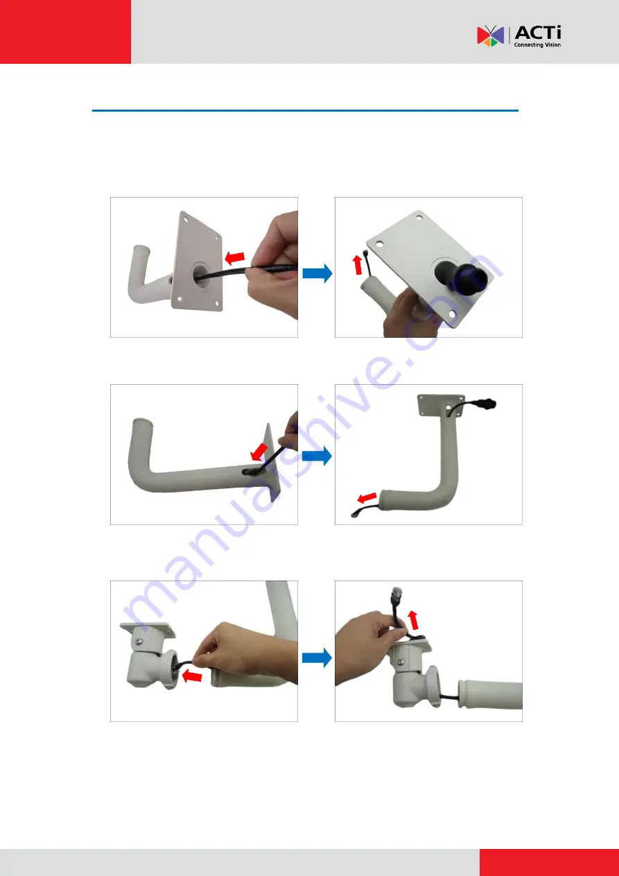
Step 3: Insert the Cable Through the Ceiling Bracket 

1.


Determine how the cable will be routed: 

pass through the ceiling

 or 

along the ceiling


If the cable will pass through the ceiling

, insert the “pigtail” through the top hole of 

the ceiling bracket.


If the cable will be routed along the ceiling

insert the “pigtail” through the side 

hole of the ceiling bracket.


2.


Insert the “pigtail” through the main bracket. 


Summary of Contents for B4 Series

Page 1: ...2014 05 06 Bullet with Integrated Bracket B4x Mounting on a Hard Ceiling using the Ceiling Bracket Installation Guide For Models B41 B44 B45 B47 ...

Page 2: ...8 Step 5 Attach the Ceiling Bracket to the Camera 9 Step 6 Install the Camera to the Ceiling 10 Step 7 Waterproof and Connect the Network Cable 11 Step 8 Connect to Network 11 Step 9 Access the Camera Live View 11 Step 10 Adjust the Viewing Angle and Focus 12 Waterproof Solution Using the Pigtail 13 How to Use the Female Cable Gland 14 How to Use the Female Conduit Gland 17 Appendices 21 How to Ac...

Page 3: ...ews separately according to the material of the ceiling where the camera will be installed IMPORTANT Before installation make sure the ceiling can bear more than the weight of the camera and its bracket Step 1 Disconnect the Ethernet Cable Before replacing the integrated bracket the network cable or pigtail must be disconnected and removed from the camera first 1 Loosen the four 4 screws to remove...

Page 4: ...allation Guide 4 Step 2 Remove the Integrated Bracket 1 Using the bundled camera base wrench detach the two 2 screws to remove the bracket 2 Remove the clamping nut and sealing insert 3 Pull the pigtail from the camera ...

Page 5: ... Guide 5 4 Remove the sealing insert and clamping nut from the cable and then pull out the pigtail from the bracket 5 Loosen the two 2 screws using the bundled bracket wrench to detach the bracket B from the main bracket A A B ...

Page 6: ... be routed pass through the ceiling or along the ceiling If the cable will pass through the ceiling insert the pigtail through the top hole of the ceiling bracket If the cable will be routed along the ceiling insert the pigtail through the side hole of the ceiling bracket 2 Insert the pigtail through the main bracket ...

Page 7: ...www acti com Installation Guide 7 3 Insert the clamping nut into the Ethernet cable 4 Insert the sealing insert with the claw ...

Page 8: ...he Cable to the Camera 1 Insert the Ethernet cable through the bottom hole of the camera 2 Pull the cable towards the back of the camera and then connect the cable to the Ethernet port 3 Tighten the four 4 screws to attach the back cover to the camera ...

Page 9: ...h the clamping nut NOTE Make sure the clamping nut is tightly attached to the gland body and the sealing insert is squeezed tightly 2 Secure the two 2 screws using the bundled bracket wrench to attach the main bracket to the camera 3 Push the excess length of cable through the ceiling bracket and align the ceiling bracket to the main bracket ...

Page 10: ...late If the cable will pass through the ceiling drill the cable hole and route the network end of the camera through that cable hole Otherwise simply attach the camera to the ceiling using four 4 screws NOTE Screws for ceiling installation are not supplied with the camera nor the ceiling bracket package Purchase applicable screws separately according to the material of the ceiling where the camera...

Page 11: ...wer source See Power over Ethernet PoE example connection diagram below Network AC Power Source PoE Injector PoE Switch Power Cable Ethernet Cable Ethernet Cable Data Power Ethernet Cable Data Camera In case of using a non PoE switch power up the camera using a power adapter not supplied See the camera Hardware Manual downloaded from our website www acti com for more information on connecting othe...

Page 12: ... Do the following Using the bundled bracket wrench do the following 1 Loosen the tilt adjustment screws adjust the camera tilt and then tighten back the screws to fix the tilt position 2 Loosen the pan adjustment screw move the pan direction and then tighten back the screw to fix the pan position Pan Adjustment Screw Tilt Adjustment Screw ...

Page 13: ...etween the camera and a Power over Ethernet PoE switch or injector See How to Use the Female Cable Gland on page 14 Female Conduit Gland Use this solution when connecting a standard indoor Ethernet cable between the camera and a Power over Ethernet PoE switch injector A flexible conduit trade size 1 2 is required to house the Ethernet cable See How to Use the Female Conduit Gland on page 17 NOTE T...

Page 14: ...le connections see related installation procedures for details Before connection prepare the following materials Female Cable Gland included in the camera package Exterior Grade Ethernet Cable not included in the package NOTE Exterior grade cables are already waterproof Not included in the package Washer included in the camera package Perform the following to waterproof the pigtail using the femal...

Page 15: ...Installation Guide 15 2 Insert the clamping nut into the Ethernet cable 3 Insert the sealing insert with claw 4 Insert the gland body into the Ethernet cable 5 On the pigtail side insert the washer into the pigtail ...

Page 16: ...NOTE Make sure the gland body is tightly attached to the pigtail and the washer is secured between them 8 Insert the sealing insert into the cable gland body and then attach the clamping nut to complete the cable solution NOTE Make sure the clamping nut is tightly attached to the cable gland body and the sealing insert is squeezed tightly ...

Page 17: ...rst before doing the cable connections see related installation procedures for details Before connection prepare the following materials Female Conduit Gland included in the camera package Flexible Conduit 1 2 Trade size not included in the package NOTE Not included in the package Washer included in the camera package Ethernet Cable CAT 5 or CAT 6 not included in the package Perform the following ...

Page 18: ...able through the flex conduit Leave enough length of the cable outside the flex conduit 3 Insert the clamping nut into through the flex conduit 4 Insert the sealing nut and fix it at the end of the flex conduit 5 Insert the gland body into the Ethernet cable ...

Page 19: ...ail side insert the washer into the pigtail 7 Connect the Ethernet cable connector to the pigtail connector 8 Attach the gland body to the pigtail NOTE Make sure the gland body is tightly attached to the pigtail and the washer is secured between them ...

Page 20: ...h the flex conduit and insert the sealing nut into the gland body NOTE Make sure the clamping nut is tightly attached to the cable gland body and the sealing insert is squeezed tightly 10 Attach the clamping nut to complete the cable solution ...

Page 21: ...n the same network segment In most cases it means that they both should have very similar IP addresses where only the last number of the IP address is different from each other There are 2 different approaches to IP Address management in Local Area Networks by DHCP Server or Manually Using DHCP server to assign IP addresses If you have connected the computer and the camera into the network that ha...

Page 22: ...local area network will be discovered by Windows thanks to the UPnP function support of our cameras In the example below we successfully found the camera model that we had just connected to the network By double clicking the mouse button on the camera model it is possible to automatically launch the default browser of the PC with the IP address of the target camera filled in the address bar of the...

Page 23: ...addresses serial numbers firmware versions etc and allows quick configuration of multiple devices at the same time The IP Utility can be downloaded for free from http www acti com IP_Utility With just one click you can launch the IP Utility and there will be an instant report as follows You can quickly notice the camera model in the list Click on the IP address to automatically launch the default ...

Page 24: ... network and it does not detect any DHCP services it will automatically assign itself a default IP 192 168 0 100 Whereas the default port number would be 80 In order to access that camera the IP address of the PC has to be configured to match the network segment of the camera Manually adjust the IP address of the PC In the following example based on Windows 7 we will configure the IP address to 19...

Page 25: ... IP Utility With the procedure shown above all the cameras will have unique IP addresses starting from 192 168 0 101 In case there are 20 cameras selected the last one of the cameras would have the IP 192 168 0 120 Later by pressing the Refresh button of the IP Utility you will be able to see the list of cameras with their new IP addresses Please note that it is also possible to change the IP addr...

Page 26: ...onfigurations Yes Yes QuickTime http www apple com quicktime download has to be installed in PC first before using any non Internet Explorer browsers to be able to get live video feed from the camera with those browsers It is a free and open source cross platform multimedia player Disclaimer Notice The camera manufacturer does not guarantee the compatibility of its cameras with QuickTime since it ...

Page 27: ... following address into Web browser s address bar http 192 168 0 100 Upon successful connection to the camera the user interface called Web Configurator would appear together with the login page The HTTP port number was not added behind the IP address since the default HTTP port of the camera is 80 which can be omitted from the address for convenience Before logging in you need to know the factory...

Page 28: ...e care has been taken during the writing of this manual Please inform your local office if you find any inaccuracies or omissions We cannot be held responsible for any typographical or technical errors and reserve the right to make changes to the product and manuals without prior notice Cleaning Disconnect this video product from the power supply before cleaning Attachments Do not use attachments ...

Page 29: ...ectly exposed to rain or water 4 If the video product does not operate normally by following the operating Instructions in this manual Adjust only those controls that are covered by the instruction manual as an improper adjustment of other controls may result in damage and will often require extensive work by a qualified technician to restore the video product to its normal operation Safety Check ...

Page 30: ...Copyright 2014 ACTi Corporation All Rights Reserved 7F No 1 Alley 20 Lane 407 Sec 2 Ti Ding Blvd Neihu District Taipei Taiwan 114 R O C TEL 886 2 2656 2588 FAX 886 2 2656 2599 Email sales acti com ...

Reviews: