background image

Level Gauge A1207D

User Manual 

4

7 OPERATION ....................................................................................................................................................................15

7.1 COUPLANT .........................................................................................................................................................................................................15
7.2 PROBE CONNECTION ..............................................................................................................................................................................15
7.3 SWITCHING ON .............................................................................................................................................................................................16
7.4 FUNCTIONAL CHECK ...............................................................................................................................................................................16
7.5 CHANGING THE DIMENSIONAL UNIT .........................................................................................................................................17
7.6 MEASUREMENT ............................................................................................................................................................................................17
7.7 SWITCHING OFF ...........................................................................................................................................................................................17
7.8 STORAGE ............................................................................................................................................................................................................17

8 TROUBLESHOOTING ..................................................................................................................................................18
9 MEASURES AT THE END OF THE LIFETIME OF THE EQUIPMENT ..........................................................19

Summary of Contents for A1207D

Page 1: ...Level Gauge A1207D User Manual 1 ACOUSTIC CONTROL SYSTEMS ULTRASONIC MEASURING DEVICE FOR GEAR OIL LEVEL Acoustic Control Systems ACS Group Saarbrücken Germany 2019 A1207D LEVEL GAUGE USER MANUAL ...

Page 2: ...COUSTIC CONTROL SYSTEMS ACS Solutions GmbH Science Park 2 66123 Saarbrucken Germany Phone 49 0 681 96592270 Fax 49 0 681 96592280 Е mail info acs international com Website www acs international com Issue date 09 17 2018 Service Address ...

Page 3: ...ECHARGEABLE BATTERY 8 2 DEVICE USAGE AND LIMITATIONS 10 2 1 APPROPRIATE USE 10 2 2 REASONABLY FORESEEABLE MISUSE 11 3 SAFETY 12 4 MAINTENANCE AND REPAIR 13 4 1 PREVENTIVE MAINTENANCE 13 4 2 CONTROL PROCEDURES AND TEST EQUIPMENT 13 4 3 DOCUMENTATION OF MAINTENANCE 13 4 4 REPAIR 13 5 INITIAL STEP FOR TROUBLESHOOTING 14 6 TECHNICAL SPECIFICATION 14 ...

Page 4: ...1 COUPLANT 15 7 2 PROBE CONNECTION 15 7 3 SWITCHING ON 16 7 4 FUNCTIONAL CHECK 16 7 5 CHANGING THE DIMENSIONAL UNIT 17 7 6 MEASUREMENT 17 7 7 SWITCHING OFF 17 7 8 STORAGE 17 8 TROUBLESHOOTING 18 9 MEASURES AT THE END OF THE LIFETIME OF THE EQUIPMENT 19 ...

Page 5: ...t into water After contact with clear water wipe it thoroughly with a clean soft cloth Contact of the device with liquids other than water may adversely affect the performance and appearance of the device Dropping the device and opening it by unqualified personnel may affect the solid particle protection Tests with this device type in a controlled environment have shown that the requirements of EN...

Page 6: ...ories will result in poor performance and malfunctions not covered by the warranty The device has a casing seal Breaking the seal leads to a loss of warranty Changes in appearance and technical speci fications are subject to change without previous notification 1 1 SCOPE OF DELIVERY 1 Service check book User Manual USB Cable Measuring Device with Safety Strap Compartment for Couplant LEMO Cable Pr...

Page 7: ... 7 ACOUSTIC CONTROL SYSTEMS 1 2 MAIN COMPONENTS 1 Mains Plug USB Socket USB Socket Charging Cable Bayonet Connector Rubber sealing ring Probe Connector Connecting Cable Instrument Display Light Light ON OFF Switch Steckerverbindung ...

Page 8: ...and must be replaced Use only ACS approved chargers batteries and cables Unauthorized chargers or cables may cause the battery to explode or damage the device Incorrect connection of the charger may cause serious damage to the device Damage caused by improper use is not covered by the warranty 1 Connect one end of the USB cable to the USB power supply and the other end to the multifunction jack 2 ...

Page 9: ...g charged A moderate increase of temperature during charging procedure is not critical In the case of a drastic temperature rise on the other hand the charging unit must be removed at once The charger does not have an on off switch So you need to disconnect the charger from the power socket when not in use to prevent wasting energy It is advisable to install the charging unit close to the mains co...

Page 10: ...ment trained in work safety for the corresponding area Measurement of gear oil level in cars Apprentices Trainees Students 16 years Trained in handling of measurement equipment trained in work safety for the corresponding area Measurement of gear oil level in cars Public e g visitors No user group The handling of the measuring device is prohibited for these persons Vulnerable persons e g pregnant ...

Page 11: ...ated by trained personnel Nevertheless misuse is not excluded if care is not taken For troubleshooting see Chapter 8 Troubleshooting Problem cause Consequence Incorrect use of the calibration block coupling and determina tion of temperature compensation Incorrect measurement Inadequate couplant Incorrect measurement Excessive quantity of couplant Incorrect measurement Insufficient quantity of coup...

Page 12: ... over to persons not aware of inherent risks or not knowing the content of this manual Be sure to stand securely when measuring with the device Pay attention to your environment and potential hazards during the measurement Motor components and the underside of the car may be hot protective clothing may be required and avoid contact with hot surfaces Cars are always subject to contamination by oil ...

Page 13: ...ouplant Check for damage Once per year Device cable probe Inspection and calibration by ACS or authorized dealer For this measuring device calibration is imperative It should be included in the measuring equip ment monitoring of the enterprise 4 1 PREVENTIVE MAINTENANCE Correct functionality is inspected by means of the calibration block contained in the set The procedure is detailed in section 7 ...

Page 14: ...he device USB3 Connection Device material supply Couplant to be applied by user Time Limits Uninterrupted operation Hours 16 hours max Lifetime for device and probe Hours 18 000 Functionality check Before each use Cleaning After each use Inspection Once per year General description Dimensions mm 125 x 25 x 15 Weight g 40 Display mm 30 x 10 Display update rate Hz 10 Probe connection LEMO 0 Operatin...

Page 15: ...ories for temperature measurement are not included in the delivery Nominal values with respect to temperature are supplied by the manufacturer of the workshop diagnosis equipment Inappropriate temperature determination and or an incorrect correction value table can lead to incorrect measurements and the resulting consequential damage ACS is not liable for any damage or loss whether contractually o...

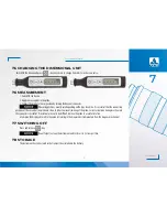
Page 16: ...ome couplant to the probe 2 Calibration block and probe must be mutually connected by insertion into the bay onet connector and careful turning 3 Switch ON the device 4 The value displayed must be within the range of the values specified on the cali bration block label 5 If the value is out of tolerance refer to troubleshooting section 8 2 or consult fac tory service 7 3 SWITCHING ON Press and rel...

Page 17: ...ending on the type of vehicle It is essential that the connecting positions at the car and at the probe are clean In order to prevent jamming of the probe correct orientation during insertion into the connector is essential If insertion turns out to be difficult remove the probe in a careful rotation 4 Compare the displayed result to the value correlating to the measured oil temperature from the d...

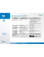
Page 18: ...t Improper couplant Replace couplant Incorrect measurement Excessive quantity of couplant Remove some couplant No signal Insufficient quantity of couplant Add some couplant Incorrect measurement no result The probe has been introduced in a ske wed manner into the guide of the oil pan Detach the probe Insert it again correctly oriented No signal Damaged probe Probe must be replaced No signal Damage...

Page 19: ... guidelines for the separationofelectricalandelectronicproducts Theproperdisposalofyouroldproductprotectsagainstpotential and negative effects on the environment and human health Battery disposal Your product includes a built in rechargeable battery that is covered by European Directive 2006 66 EC which states that the battery should not be disposed of with normal domestic waste Please refer to th...

Page 20: ...Level Gauge A1207D User Manual 20 ACOUSTIC CONTROL SYSTEMS NOTES ...

Page 21: ...Level Gauge A1207D User Manual 21 ACOUSTIC CONTROL SYSTEMS NOTES ...

Page 22: ...Level Gauge A1207D User Manual 22 ACOUSTIC CONTROL SYSTEMS NOTES ...

Page 23: ...Level Gauge A1207D User Manual 23 ACOUSTIC CONTROL SYSTEMS ...

Page 24: ...Level Gauge A1207D User Manual 24 ACOUSTIC CONTROL SYSTEMS USER MANUAL ULTRASONIC MEASURING DEVICE FOR GEAR OIL LEVEL A1207D LEVEL GAUGE Acoustic Control Systems ACS Group Saarbrücken Germany 2019 ...

Reviews: