SERIES AP440 ACROPACK
USER
’S MANUAL
Acromag, Inc. Tel: 248-295-0310
- 24 - http://www.acromag.com
- 24 -
www.acromag.com
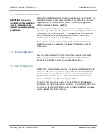
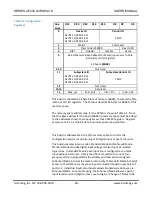
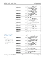
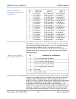
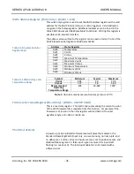
Module Location In System Register (Read Only) - (BAR0 + 0x0000 0004)
This read only register is used identify the module’s plugin location in a
system.
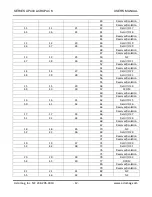
Table 3.8 Location Register
Note that any registers/bits not
mentioned will remain at the
default value logic low.
Bit(s)
FUNCTION
2 to 0
Module Site Location Bits. These bits identify the location on
the carrier of the AP module.
000
Carrier Site A
001
Carrier Site B
010
Carrier Site C
011
Carrier Site D
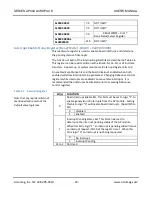
7 to 3
Module Slot Location Bits. These bits identify the slot location
of the AP module in a system. The Carrier may use backplane
signals as in a VPX system or a carrier DIP switch to uniquely
identify the system location of the carrier.
XXXXX
System Slot identification bits are described by the
AcroPack carrier card.
31 to 8 Not Used
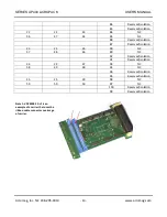
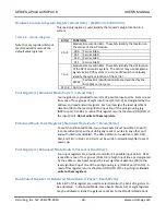
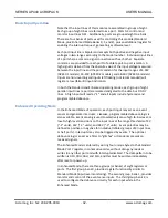
Port Registers (Standard Mode Ports 0-3, Read Only)
Four registers are provided to monitor 32 possible input points. Data is read
from one of four groups of eight input lines (Ports 0-3), as designated by the
address and read and write signals. Each port assigns the least significant
data line (D0) to the least significant input line of the port grouping (e.g.
IN00 for port 0 to D0). A read of this register returns the status (ON/OFF) of
the input point. Do not write to these registers.
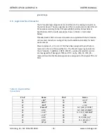
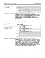
Enhanced Mode Select Register (Standard Mode Ports 7, Read/Write)
To switch to Enhanced Mode, four unique bytes must be written to port 7,
in consecutive order, without doing any reads or writes to any other port
and with interrupts disabled. The data pattern to be written is 07H, 0DH,
06H, and 12H, in order, and this must be written immediately after reset or
power-up.
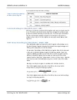
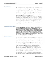
Port Registers (Enhanced Mode Bank 0, Ports 0-3, Read Only)
Four input registers are provided to monitor 32 possible input points. Data
is read from one of four groups (Ports 0-3) of eight input lines, as designated
by the address. Each port assigns the least significant data line (D0) to the
least significant input line of the port grouping (e.g. IN00 of port 0 to D0). A
read of this register returns the status (ON/OFF) of the input signal. Do not
write to these registers.
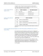
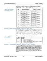
Bank Select Register 0 (Enhanced Mode Bank 0, Ports 7, Read/Write)
Bits 6 & 7 of this register are used to select/monitor the bank of registers to
be addressed. In Enhanced Mode, three banks (banks 0-2) of eight registers
may be addressed. Bank 0 registers are similar to the Standard Mode bank

