-11-
V. MOUNTING AND CONNECTING THE PANEL
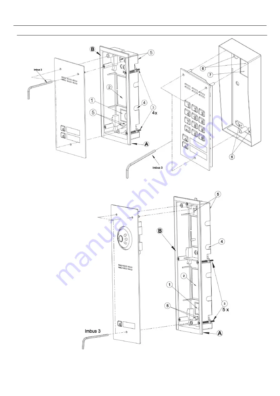
ASSEMBLY
The panel should be assembled so as to minimise the impact of adverse weather conditions, in
particular water.
Allen key 3
Page 1: ...1 DOOR ENTRY SYSTEMS EXTENDED USER INSTRUCTION OF FAM P AND FAM PV DOOR ENTRY SYSTEMS 62 002 Suchy Las ul Diamentowa 7 tel fax 61 843 93 71 www aco com pl...
Page 2: ...ccess code 32 Modification of administrator s initial access code 33 2 SETTING E LOCK OPENING TIME 33 3 SETTING THE NUMBER OF RINGTONES PERMISSION TO CALL APARTMENT 33 4 TURNING ON OFF THE DOOR OPENIN...
Page 3: ...he opening code resident administrator 2 Setting E lock reset time 3 Setting the number of ringtones permission to call apartment 4 Turning the door opening signal off on 5 Setting one of four rington...
Page 4: ...c keypad while all settings are available via FAM_P computer program PC Windows Adding deleting archiving transferring between panels proximity fobs can be done using the ACC_v3 software PC Windows In...
Page 5: ...e customised to individual requirements Adjustable camera position in each direction FAM PV panels Option of image viewing in darkness infrared illumination FAM PV panels Support for proximity key fob...
Page 6: ...addresses from the bottom address 1 bottom button and successively up to address 6 top button It is also possible after changing the settings via the PC program or directly on the panel numeric keypa...
Page 7: ...d It is possible to open without having to connect with the apartment In this case on classic uniphones the handset must be picked up and the open button pressed three times on active receivers INS UP...
Page 8: ...ervice program 9 By default the code table is only added to panels FAM P ZS and FAM PV ZS For other versions of the panel use the code table that is used in the panel master panel or generate it using...
Page 9: ...sed for opening via an additional module such as an I O module The module is connected to the EXTMOD socket on the panel board and configured via the PC program Automatic opening when calling an addit...
Page 10: ...XI CDN U signalling module with opening function This module can be used to connect additional devices signalling ringing in the apartment for instance additional bells light bulbs signallers etc for...
Page 11: ...11 V MOUNTING AND CONNECTING THE PANEL ASSEMBLY The panel should be assembled so as to minimise the impact of adverse weather conditions in particular water Allen key 3 Allen key 3 Allen key 3...
Page 12: ...s where the camera lens may be exposed to direct perpendicular light from the sun street lamps etc 2 CONNECTING THE PANEL All connections in the installation must be soldered The following wires need...
Page 13: ...cross section with 1 mm2 wire the distance can be increased to 400 m with 1 5 mm2 wire the distance can be increased to 600 m with 2 5 mm2 wire the distance can be increased to 1000 m Use CDNV RJ45 m...
Page 14: ...number of receivers in the entire system detailed information can be found in the assembly instructions for the active receivers used In the case of video panels the wiring between the panel and the...
Page 15: ...stalled in the panel available under the panel terminals When working with reversible E locks voltage appears on ELOCK output depending on transformer or DC power supply used 15VDC use suitable revers...
Page 16: ...16 3 WIRING DIAGRAMS FOR SINGLE PANEL INSTALLATION Audio panel installation with passive receivers should be connected as per the diagram below Line Line Line Line...
Page 17: ...17 The installation of audio panels with active receivers should be connected as per the diagram below...
Page 18: ...18 The installations of audio panel with additional external camera and monitors should be connected as per the diagram below To monitor or splitter...
Page 19: ...ting the bus cable orange and brown together to DC terminal of the panel in this case the maximum distance between the panel and the monitor is 70m If the additional power supply is connected directly...
Page 20: ...20 Video Panel with several monitors should be connected as per the diagram below Rozdzielacz Splitter Rozdzielacz Splitter...
Page 21: ...he panel microphone using the MIC potentiometer adjust the panel speaker volume level using the SPK potentiometer As the MIC and SPK values are set turn the BALANCE potentiometer to determine the posi...
Page 22: ...of the busy panels Calling and connection topology of Slave panels is shown in the figure below where A is the Master panel B C D E F are Slave panels Only those receivers that are physically connect...
Page 23: ...he first Familio master panel If several Familio audio panels are installed two bus wires are arranged to the first panel Line Line and Line are connected to the ML terminal of the next panel Line to...
Page 24: ...or opening codes will be the same for all apartments For proper operation of a system with multiple panels configuration is required for the number and range of apartment addresses that a panel is to...
Page 25: ...25 Installation of multiple audio panels with active receivers should be connected as per the diagram below...
Page 26: ...multiple audio panels with additional external camera and multiple monitors should be connected as per the diagram below Rozdzielacz Splitter Kolejne pi tra Next floors Sumator bez kamery Intermediate...
Page 27: ...27 Installation with multiple video panels and monitors should be connected as per the diagram below Rozdzielacz Splitter Sumator po redni do FAM PV Intermediate combiner for FAM PV...
Page 28: ...mator po redni do FAM PV Intermediate combiner for FAM PV Rozdzielacz Splitter Rozdzielacz Splitter Rozdzielacz Splitter Sumator po redni do FAM PV Intermediate combiner for FAM PV Sumator bez kamery...
Page 29: ...er for FAM PV Klatka budynek X Staircase building X Kolejne pietra Next floors Kolejne pietra Next floors Klatka budynek Y Staircase building Y Rozdzielacz Splitter Sumator po redni do FAM PV Intermed...
Page 30: ...30 Installation with two panels the first of which is an Audio panel should be connected as per the diagram below example 4 Kolejne pietra Next floors Rozdzielacz Splitter...
Page 31: ...he panel such as individual access codes opening time ringtone etc Service programs are also available to facilitate installation and repairs Basic parameters can be changed using the service menu acc...
Page 32: ...LE To enter the panel programming function with 0000 installer s code press the key followed by 1507 fixed digits and 0000 1 5 0 7 0 0 0 0 Entering the programming mode is confirmed by an up modulated...
Page 33: ...ting time from 1s to 10s by entering a digit between 0 and 9 0 means 10 seconds When the panel is reset to factory settings the time is set to 4s 3 SETTING THE NUMBER OF RINGTONES PERMISSION TO CALL A...
Page 34: ...partment With the receiver s handset lifted press the door opening button three times for passive receivers or press the door opening button once for active receivers The panel will confirm receipt of...
Page 35: ...dents are set across the whole system For panels with only a numeric keypad the code table number is entered in accordance with the code table supplied Any code table can be generated and name tag pri...
Page 36: ...code Enabling the restriction of the administrator s code from 6 to 4 digits Doorman s call Enabling the doorman s call by shorting the INPUT Call only button Permitting calls only from direct call b...
Page 37: ...No 1 or 2 or 3 E lock triggering time as for standard opening Activation of the OUTPUT for a pre set time after pressing the F2 key on the uniphone or after selecting the code preceded by the double p...
Page 38: ...itional number 1 Address Physical address to which the panel will call after dialling the additional number Tone Ringtone in the apartment after dialling the additional number Number of ringtones Numb...
Page 39: ...e CDNP INSPIRO i e calls can be made directly from the numeric keypad and the codes must be preceded by the apartment number and the button of the button Once the factory settings are successfully res...
Page 40: ...surface causing abrasion of its natural protective coating and increasing the risk of corrosion XVI SAFETY RULES FOR INSTALLATION AND USE Installation should be carried out by a qualified installer B...
Page 41: ...12V between GND and ELOCK terminal Each panel in the system must feature a separate power supply Door opening signalled by the unit but E lock won t work Check E lock or E lock connection to the panel...