background image

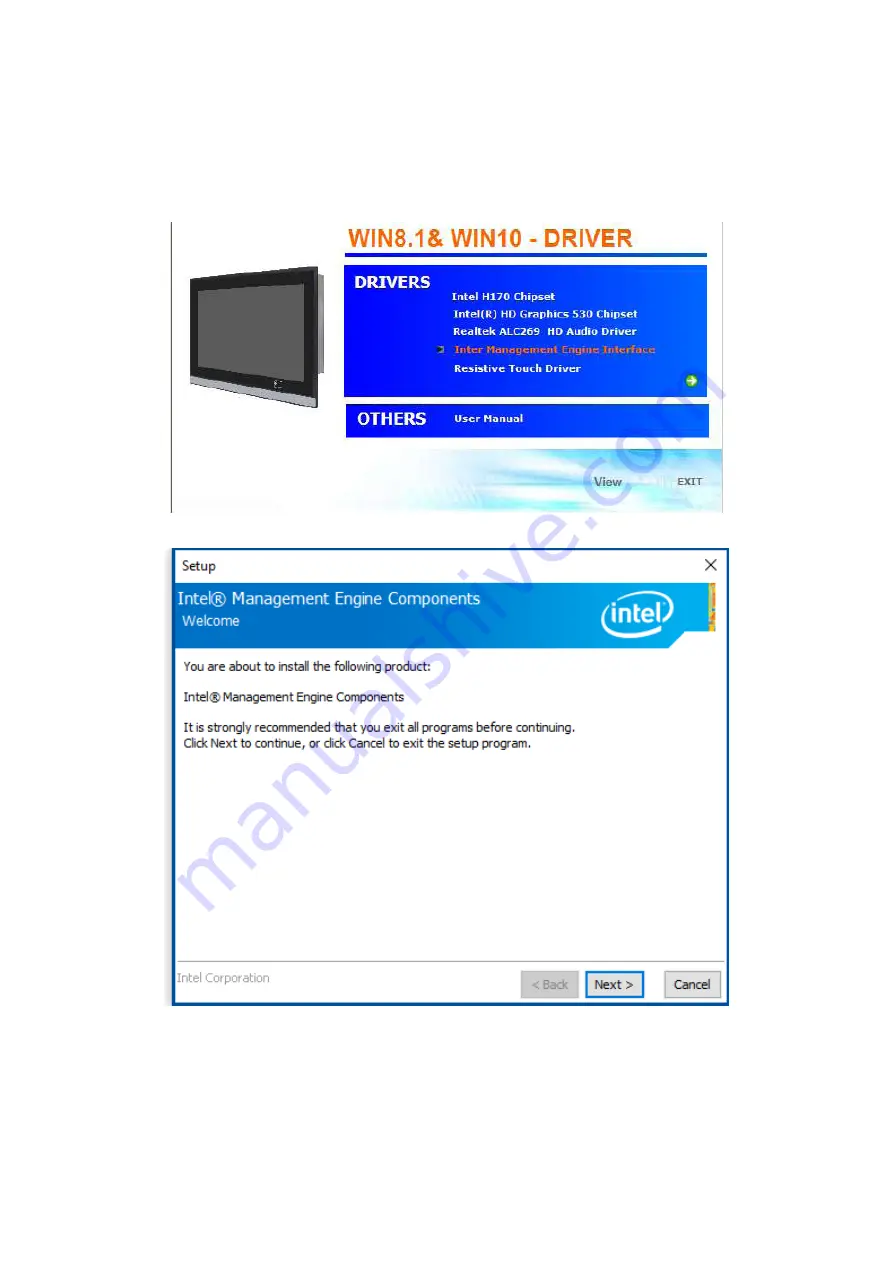
4.4 Intel Management Engine Interface 

To install the Intel Management Engine Interface, please follow the steps below. 

Step 1.

 Select 

Intel Management Engine Interface

 from the list 

Step 2.

 Select setup language you need. Click 

Next

 to continue. 

68

Summary of Contents for PCA80 Series

Page 1: ...Bezel Embedded Computers All rights reserved Product description and product specifications are subject to change without notice For latest product information please visit Acnodes website at www acnodes com Copyright 2019 Acnodes Corp User Manual 14628 Central Ave Chino CA 91710 Tel 909 597 7588 Fax 909 597 1939 1 ...

Page 2: ... Version 1 1 2018 01 25 Modify PCIe information Renew product images 1 2 2018 06 01 Modify Core I 7 motherboard BIOS chapter 1 3 2018 06 08 SW1 6 1 4 2019 01 02 Modify front bezel information 1 5 2019 10 25 Revise product images dimensions and mechanical information 2 ...

Page 3: ...ric Shock Hazard Do not operate the machine with its back cover removed There are dangerous high voltages inside This equipment will generate use and radiate radio frequency energy and if not installed and used in accordance with the instructions manual it may cause interference to radio communications It has been tested and found to comply with the limits for a Class A computing device pursuant t...

Page 4: ... from damage Avoid your system from static electricity on all occasions Prevent electric shock Don t touch any components of this card when the card is power on Always disconnect power when the system is not in use Disconnect power when you change any hardware devices For instance when you connect a jumper or install any cards a surge of power may damage the electronic components or the whole syst...

Page 5: ...nectors Location 20 2 4 Jumpers Setting and Connectors 22 Chapter 3 BIOS Setup 3 1 Operations after POST Screen 38 3 2 BIOS setup utility 38 3 3 Main Setting 39 3 4 Advanced Settings 40 3 5 Chipset Settings 46 3 6 Security Settings 53 3 7 Boot Settings 54 3 8 Save Exit Settings 55 Chapter 4 Installation of Drivers 4 1 Intel H170 Chipset Driver 58 4 2 Intel R HD Graphics 530 Chipset Driver 61 4 3 R...

Page 6: ...15 10 Figure 1 5 Front View of PCA80150 80170 11 Figure 1 6 Front View of PCA80156 80215 12 Figure 1 7 Rear View of PCA80150 80156 12 Figure 1 8 Rear View of PCA80170 12 Figure 1 9 Rear View of PCA80215 13 Figure 2 1 Motherboard ASB M8171 Layout 19 Figure 2 2 Motherboard top draw of ASB M8171 20 Figure 2 3 Motherboard bottom draw of ASB M8171 21 6 ...

Page 7: ...4 6th 7th Gen Intel Core Processor 6th i7 6700TE Quad 3 4GHz 6th i5 6500TE Quad 3 3GHz 6th i3 6100TE Dual 2 4GHz 6th Pentium G4400TE Dual 2 4GHz 6th Celeron G3900TE Dual 2 3GHz 7th i7 7700T Quad 2 9GHz 7th i7 7500T Quad 2 7GHz 7th i7 7101TE Quad 3 4GHz 7th Celeron G3930TE Dual 2 7GHz System Chipset Intel 100 Series Chipset H170 Default System Memory 2 x 260 pin SO DIMM up to 32GB DDR4 2133MHz SDRA...

Page 8: ... default 1 x SIM slot for option 1 x PCIe x 1 and 1 x PCIe x 16 slot 1 x WIFI Bluetooth LTE and antenna at rear side for option LCD Display type 15 color TFT LCD 15 6 color TFT LCD 17 color TFT LCD 21 5 color TFT LCD Max Resolution 1024 x 768 1366 x 768 1920 x 1080 1280 x 1024 1920 x 1080 Max Color 16 7M 16 7M 16 7M 16 7M Luminance cd m2 420 300 350 250 Contrast Ratio 800 1 500 1 1000 1 3000 1 Vie...

Page 9: ...zel Aluminum die casting front bezel Rear bezel Steel metal chassis Dimension 410 x 310 x 90 mm 412 x 277x 90 mm 439 x 348 x 90 mm 557 x 362 x 90 mm Net Weight 6 5 Kg 6 5 kg 7 kg 8 5 kg Mounting type Panel mount Environmental Operating Temperature 0 50 C Storage Temperature 30 70 C Storage Temperature 10 95 40 C non condensing Certificate CE FCC Class A Operating System Support OS Support Windows ...

Page 10: ...1 3 Dimensions Figure 1 1 Dimensions of PCA80150 Figure 1 2 Dimensions of PCA80156 10 ...

Page 11: ...Figure 1 3 Dimensions of PCA80170 Figure 1 4 Dimensions of PCA80215 11 ...

Page 12: ...lity for critical utilizations Besides they feature abundant I O ports such as 4 x USB 3 0 1 x VGA 2 x LAN 1 x line out 1 x mic in 3 x COM ports and so on and 2x expansion slots which offer the expandability to integrate versatile applications Provide projected capacitive resistive touch screen and anti reflection glass screen wide range DC 9 36V power input AT ATX model and panel mount These syst...

Page 13: ...Figure 1 6 Front View of PCA80156 80215 Figure 1 7 Rear View of PCA80150 80156 Figure 1 8 Rear View of PCA80170 13 ...

Page 14: ...80215 1 5 Installation of HDD Step 1 There are 4 screws to deal with when enclosing or removing the chassis Gently remove 4 screws Step 2 Remove the chassis Step 3 There are 4 screws around HDD bay you can remove screws of HDD 14 ...

Page 15: ...DD 1 6 Installation of PCIe card Step 1 There are 2 PCIe slot on the bottom side Gently remove 2 screws on side Step 2 Remove the bracket on the bottom Step 3 You can insert PCIe card to expansion model function PCIe Card maximum size can support 135mm W x 185mm L x 20 32mm 1 slot L W 15 ...

Page 16: ...ere are 4 screws to deal with when enclosing or removing the chassis Gently remove 4 screws Step 2 Remove the chassis Step 3 You can insert mSATA SSD card to expansion storage Step 4 You can use 2 screws to fasten SSD card to motherboard 16 ...

Page 17: ...to 35W Intel Core I3 6100TE 2 70GHz 35W Intel Core I5 6500TE 2 30 GHz up to 3 30 GHz 35W Intel Core I7 6700TE 2 40 GHz up to 3 40 GHz 35W Chipset Intel H170 Memory Support 2x SO DIMM 260pins up to 32GB DDR4 1866 2133MHz FSB Graphics Intel HD Graphics 530 I3 6100TE I5 6500TE I7 6700TE Display Mode 1x DVI I interface Pin header 1x HDMI interface 1x 18 24bit 2CH LVDS interface 1x VGA interface DB15 o...

Page 18: ...000mAh Audio Support Audio via Realtek ALC269Q VB HD audio codec Support Line out Line in MIC in by JACK AUDIO1 Line in Line out Mic by 2 x 6 Pin header F_AUDIO1 Support a stereo Class D Speaker Amplifier with 2 watt per channel output power by 1x4 pin header SPK1 Keyboard Mouse PS2 K B and Mouse by 1x6Pin Wafer connector 1x PS 2 keyboard 1x PS 2 mouse Expansion 1x PCI express x4 extend by 4x20 pi...

Page 19: ...M 1x SIM Card Holder 1x 6Pin Wafer by SIM1 LPT 1x LPT Port by DF13 20P LPT1 Temperature Operating 20 to 70 Storage 40 to 85 Humidity 10 90 non condensing operating Power Consumption 12V 3 8A Intel i3 6100TE 2 30 GHz Processor with 16GB DDR4 SSD EMI EMS Meet CE FCC class A 19 ...

Page 20: ... units mm Figure 2 1 Motherboard ASB M8171 Layout 2 2 Motherboard Layout 20 ...

Page 21: ...2 3 Jumpers and Connectors Location Board Top Figure 2 2 Motherboard top draw of ASB M8171 21 ...

Page 22: ...Board Bottom Figure 2 3 Motherboard bottom draw of ASB M8171 22 ...

Page 23: ...lts e After the above operations save changes and exit BIOS Setup 2 BAT1 1 25mm Pitch 1x2 wafer Pin Header 3 0V Li battery is embedded to provide power for CMOS Pin Signal Name Pin1 Ground Pin2 VCC_RTC 3 SW1 1 Switch DC Power input setting Power on off button and Auto Power on switch setting SW1 Function DC input DC_IN1 Pin1 ON Auto Power on Default Pin1 OFF Power on Off button option 4 BT1 2 0mm ...

Page 24: ... System power output connector Pin Power output Pin1 Ground Pin2 Ground Pin3 DC 12V Pin4 DC 12V Note DC 12V Output current of the connector must not be above 1A 7 ATX_IN1 ATX Power option 2 0mm Pitch 1X3 wafer Pin Header connect PSON and 5VSB and Ground signal support ATX Power model Pin Signal Name Pin1 ATX PSON Pin2 ATX Ground Pin3 ATX 5VSB ATX Power input setting SW1 ATX Power input 24 ...

Page 25: ... connector Pin Power output Pin1 DC 12V DC12V_S0 Pin2 Ground Pin3 Ground Pin4 DC 5V DC5V_S0 Note DC 5V Output current of the connector must not be above 0 5A DC 12V Output current of the connector must not be above 1A 10 CPU1_1 LGA1151 Socket installing the 6th Generation intel Core i3 i5 i7CPU Socket 11 HS1 4 HS1 5 HS1 6 HS1 7 CPU SCREW HOLES CPU FAN SCREW HOLES Four screw holes for fixed CPU Coo...

Page 26: ...14 H1 H2 option PCH1 HeatSink Screw holes 15 DDR4_1 DDR4_2 SO DIMM 260Pin socket DDR4 memory socket the socket is located at the top of the board and supports 260Pin 1 2V DDR4 1866 2133MHz FSB SO DIMM memory module up to 32GB 16 HDMI1 HDMI 19P Connector High Definition Multimedia Interface connector 17 DVI I1 DVI I 2 0mm Pitch 2X7 Pin Header Digital Visual Interface Integrated connector Signal Nam...

Page 27: ...he same time for CRT1 and VGA1 Signal Name Pin Pin Signal Name CRT_RED 1 2 Ground CRT_GREEN 3 4 Ground CRT_BLUE 5 6 Ground CRT_H_SYNC 7 8 CRT_DDCDATA CRT_V_SYNC 9 10 CRT_DDCCLK Ground 11 12 Ground 20 SW1 3 SW1 4 Switch 18bit or 24bit LVDS setting SW1 Function Pin3 on Single Channel LVDS Pin3 off Dual Channel LVDS Pin4 on 24bit LVDS Pin4 off 18bit LVDS 21 U5 option AT24C02 DIP8 The EEPROM IC U5 is ...

Page 28: ...tial Signaling A high speed low power data transmission standard used for display connections to LCD panels Signal Name Pin Pin Signal Name VDD5 2 1 VDD5 Ground 4 3 Ground VDD3 6 5 VDD3 LB_D0_N 8 7 LA_D0_N LB_D0_P 10 9 LA_D0_P Ground 12 11 Ground LB_D1_N 14 13 LA_D1_N LA_D1_P 16 15 LA_D1_P Ground 18 17 Ground LB_D2_N 20 19 LA_D2_N LB_D2_P 22 21 LA_D2_P Ground 24 23 Ground LB_CLK_N 26 25 LA_CLK_N L...

Page 29: ...2x4 Pin Header Reserve 26 COM1 Type DB9 Rear serial port standard DB9 Male serial port is provided to make a direct connection to serial devices RS232 Default Pin Signal Name 1 DCD Data Carrier Detect 2 RXD Received Data 3 TXD Transmit Data 4 DTR Data Terminal Ready 5 Ground 6 DSR Data Set Ready 7 RTS Request To Send 8 CTS Clear To Send 9 JP1 select Setting RI 5V 12V RS422 option Pin Signal Name 1...

Page 30: ... 1 6 are used to select signal out of pin 9 of COM2 port JP2 Pin Function Close 1 2 COM2 Pin9 RI Ring Indicator default Close 3 4 COM2 Pin9 5V option Close 5 6 COM2 Pin9 12V option 28 COM2 Type DB9 Rear serial port standard DB9 Male serial port is provided to make a direct connection to serial devices RS232 Default Pin Signal Name 1 DCD Data Carrier Detect 2 RXD Received Data 3 TXD Transmit Data 4...

Page 31: ...f pin 9 of COM6 port JP3 Pin Function Close 1 2 COM6 Pin9 RI Ring Indicator default Close 3 4 COM6 Pin9 5V option Close 5 6 COM6 Pin9 12V option 31 COM6 2 0mm Pitch 2X5 Pin Header COM6 Port standard RS232 ports are provided They can be used directly via COM cable connection Signal Name Pin Pin Signal Name DCD 1 2 RXD TXD 3 4 DTR Ground 5 6 DSR RTS 7 8 CTS JP3 select Setting RI 5V 12V 9 10 NC 32 US...

Page 32: ...lity audio I O ports 34 F_AUDIO1 2 0mm Pitch 2x6 Pin Header Front Audio An onboard Realtek ALC269Q VB codec is used to provide high quality audio I O ports Line Out can be connected to a headphone or amplifier Line In is used for the connection of external audio source via a Line in cable MIC is the port for microphone input audio Signal Name Pin Pin Signal Name 5V 1 2 GND_AUD LINE OUT L 3 4 LINE ...

Page 33: ...rs are provided SATA1 and SATA2 and SATA3 transfer speed up to 6 0Gb s RAID controller supporting RAID0 RAID1 RAID5 38 SW1 6 Switch SATA or PCIE setting SW1 M PCIE1 52Pin Pin6 on PCIE7 Signal Pin6 off SATA4 Signal 39 M PCIE1 Socket 52Pin mini PCIe socket it is located at the top it supports mini PCIe devices with USB2 0 and SIM and SMBUS and PCIe signal MPCIe card size is 30 x 50 95mm Function Sup...

Page 34: ..._D2 LPT_D4 12 11 LPT_D3 LPT_D6 14 13 LPT_D5 LPT_ACK 16 15 LPT_D7 LPT_PE 18 17 LPT_BUSY 5V_S0 20 19 LPT_SLCT 44 LED1 LED2 LED3 LED5 LED1 STATUS Green LED for Motherboard Power status LED2 STATUS Green LED for Motherboard Standby Power Good status LED3 STATUS Green LED for CPU Power status LED5 STATUS Green LED for Debug status 45 LED4 LED STATUS Green LED for Motherboard Standby Power Good status Y...

Page 35: ...N Power Button MIO_PSON 36 35 USB9_P Ground 38 37 Ground Power Auto on AUTO_PSON 40 39 NC BIOS Setup Advanced NCT6106D Super IO Configuration Serial Port 3 Configuration RS 485 Mode RS 422 Mode 47 MIO2 DF13 40P Connector Front panel connector Function Signal Name Pin Signal Name Function Power LED PWR_LED 2 1 HDD_LED HDD LED Power Button Ground 4 3 USB0708_OC MIO_PSON 6 5 USB0910_OC RESET Ground 8...

Page 36: ...ion You may short them temporarily to realize system startup shutdown or awaken the system from sleep state Pin9 Pin10 BUZZER They are used to connect an external buzzer Pin25 Pin40 USB7 USB8 USB210 USB11 Front USB connector it provides four USB2 0 ports via a dedicated USB cable Each USB Type A Receptacle 2 Ports Current limited value is 2 0A If the external USB device current exceeds 2 0A please...

Page 37: ...ot 2 X Note Please correctly assemble the riser card otherwise it will burn out the motherboard If you do not know how to assemble please contact technical support 49 PCIE_16X1 option 4x30 Pin Riser Card expansion connector Can expand support one PCIeX16 or two PCIeX8 Signal ASB M8171HT PCIE_16X connector is located at the top ASB M8171HB PCIE_16X connector is located at the Bottom MODEL PC1E_16X1...

Page 38: ...l burn out the motherboard If you do not know how to assemble please contact technical support 50 TPM_U1 option TPM_U1 SLB 9665 TT2 0 MODEL TPM Function ASB M8171HT X ASB M8171HT TPM ASB M8171HB X ASB M8171HB TPM 51 DEBUG option 2 0mm Pitch 1x9 Pin Header it supports SPI signal Pin Signal Name 1 LPC_FRAME 2 LPC_AD3 3 LPC_AD2 4 LPC_AD1 5 LPC_AD0 6 Ground 7 PLT_RST_BUF1 8 CLK_24M_DEBUG 9 3P3V_S0 52 ...

Page 39: ...discharge or BIOS flashing operation Press Delete key to enter CMOS Setup After optimizing and exiting CMOS Setup 3 2 BIOS SETUP UTILITY Press Delete key to enter BIOS Setup utility during POST and then a main menu containing system summary information will appear 39 ...

Page 40: ...system time the time format is Hour 0 to 23 Minute 0 to 59 Second 0 to 59 System Date Set the system date the date format is Day Note that the Day automatically changes when you set the date Month 01 to 12 Date 01 to 31 Year 1998 to 2099 40 ...

Page 41: ...ble ACPI Auto Configuration Disabled Enabled Enable Hibernation Enabled Disabled ACPI Sleep State S3 Suspend to RAM Suspend Disabled Lock Legacy Resources Disabled Enabled S3 Video Repost Disabled Enabled ACPI Low Power S0 Idle Disabled Enabled 41 ...

Page 42: ...n Serial port Enabled Disabled Device Settings IO 2F8h IRQ 3 Change Settings Auto Serial Port 3 Configuration Serial port Enabled Disabled Device Settings IO 3E8h IRQ 7 Change Settings Auto F75111 COM3 Config RS 485 Mode RS 422 Mode Serial Port 4 Configuration Serial port Enabled Disabled Device Settings IO 2E8h IRQ 7 Change Settings Auto Serial Port 5 Configuration Serial port Enabled Disabled De...

Page 43: ...th Status CPU Temperature 32 C CPU Fan Speed 1970 RPM VCORE 1 112 V 12V 11 960V 5V 5 120V 1 5V 1 536V 3 4 4 CPU Configuration Intel R Core TM i3 6100TE CPU 2 70GHz CPU Signature 506E3 Microcode Patch 49 Max CPU Speed 2700 MHz Mix CPU Speed 800 MHz CPU Speed 2700 MHz Processor Cores 2 Hyper Threading Technology Supported Intel VT X Technology Supported Intel SMX Technology Not Supported 64 bit Supp...

Page 44: ...t 2 0 1 Core Ratio Limit Override 0 2 Core Ratio Limit Override 0 Platform PL1 Enable Disabled Platform PL2 Enable Disabled CPU C states Enabled Enhanced C states Enabled C State Auto Demotion C1 and C3 C State Un demotion C1 and C3 Package C state demotion Enabled Package C state undemotion Enabled CState Pre Wake Enabled Package C State limit AUTO CFG lock Enabled Power Limit 3 Settings Power Li...

Page 45: ...ed OROM UI Normal Delay 2 Seconds RST Force Form Disabled Aggressive LPM Support Enabled Serial ATA Port 0 Empty Software Preserve Unknown Port 0 Enabled Hot Plug Disabled External SATA Disabled Spin Up Device Disabled SATA Device Type Hard Disk Drive Topology Unknown Device Sleep Disabled SATA DEVSLEP Idle Timeout Config Disabled Serial ATA Port 1 Empty Software Preserve Unknown Port 1 Enabled Ho...

Page 46: ...leep Disabled SATA DEVSLEP Idle Timeout Config Disabled Serial ATA Port 4 Empty Software Preserve Unknown Port 4 Enabled Hot Plug Disabled External SATA Disabled Spin Up Device Disabled SATA Device Type Hard Disk Drive Topology Unknown Device Sleep Disabled SATA DEVSLEP Idle Timeout Config Disabled Serial ATA Port 5 Empty Software Preserve Unknown Port 5 Enabled Hot Plug Disabled External SATA Dis...

Page 47: ...Ooption ROM execution Network Do not launch Storage UEFI Video Legacy Other PCI devices Legacy 3 5 Chipset Settings 3 5 1 System Agent SA Configuration System Agent Bridge Name Skylake SA PCIe Code Version 1 7 0 0 VT d Supported Graphics Configuration IGFX VBIOS Version 1034 Graphics Turbo IMON Current 31 Skip Scaning of External Gfx Card Disabled 47 ...

Page 48: ...trol PWM Normal BIA Auto Spread Spectrum clock Chip Off Active CRT CRT Panel Color Depth 24 Bit Memory Information Memory RC Version 1 7 0 0 Memory Frequency 2133 MHz Total Memory 8192MB VDD 1200 DIMM 0 8192MB DIMM 1 Not Present DIMM 2 Not Present DIMM 3 Not Present Memory Timings tCL tRCD tRP tRAS 15 36 MRC ULT Safe Config Disabled Maximum Memory Frequency Auto HOB Buffer Size Auto ECC Support En...

Page 49: ...d Time Measure Disabled Lpddr Mem WL Set Set B EV Loader Disabled EV Loader Delay Enabled Fast Boot Enabled DLL Weak Lock Support Enabled Memory Thermal Configuration Memory Power and Thermal Throttling DDR PowerDown and idle counter BIOS For LPDDR Only DDR PowerDown and Idle counter BIOS REFRESH_2X_MODE Disabled LPDDR Thermal Sensor Enabled SelfRefresh Enable Enabled SelfRefresh IdleTimer 512 Thr...

Page 50: ...ry Thermal Reporting Lock Thermal Management Registers Enabled Memory Thermal Reporting Extern Therm Status Disabled Closed Loop Therm Manage Disabled Open Loop Therm Manage Disabled Thermal Threshold Settings Warm Threshold Ch0 Dimm0 255 Warm Threshold Ch0 Dimm1 255 Hot Threshold Ch0 Dimm0 255 Hot Threshold Ch0 Dimm1 255 Warm Threshold Ch1 Dimm0 255 Warm Threshold Ch1 Dimm1 255 Hot Threshold Ch1 ...

Page 51: ...Enabled Jedec Write Leveling Enabled Early Write Time Centering 2D Enabled Early Read Time Centering 2D Enabled Write Timing Centering 1D Enabled Write Voltage Centering 1D Enabled Read Timing Centering 1D Enabled Dimm ODT Training Enabled Max RTT_WR ODT Off DIMM RON Training Enabled Write Drive Strength Equaliztion 2D Disabled Write Slew Rate Training Enabled Read ODT Training Enabled Read Equali...

Page 52: ... Disabled PCIe USB Glitch W A Disabled PCIe Function swap Enabled PCI Express Gen3 Eq Lanes Override SW EQ settings Disabled PCI Express Root Port 1 PCI Express Root Port 2 PCI Express Root Port 3 PCI Express Root Port 4 PCI Express Root Port 5 PCI Express Root Port 6 PCI Express Root Port 7 PCI Express Root Port 8 PCI Express Root Port 9 PCI Express Root Port 10 PCI Express Root Port 11 PCI Expre...

Page 53: ...ut setting Low F75111 GPIO21 Output F75111 GPIO21 Output setting Low F75111 GPIO22 Output F75111 GPIO22 Output setting Low F75111 GPIO23 Output F75111 GPIO23 Output setting Low F75111 GPIO24 Output F75111 GPIO24 Output setting Low F75111 GPIO25 Output F75111 GPIO25 Output setting Low F75111 GPIO26 Output F75111 GPIO26 Output setting Low F75111 GPIO27 Output F75111 GPIO27 Output setting Low 53 ...

Page 54: ...rect access to BIOS setup without typing any password after system reboot once the password is disabled Once the password feature is used you will be requested to type the password each time you enter BIOS setup This will prevent unauthorized persons from changing your system configurations Also the feature is capable of requesting users to enter the password prior to system boot to control unauth...

Page 55: ... 7 Boot Settings Setup Prompt Timeout 1 Bootup Numlock State On off Quiet Boot Disabled Enabled Boot Option Priorities Fast Boot Disabled Enabled New Boot Option Policy Default Place First Place Last 55 ...

Page 56: ...aving Quit without saving Yes No Save Changes and Reset Reset the system after Saving The changes Yes No Discard Changes and Reset Reset system setup without Saving any changes Yes No Save Changes Save Setup done so far to any of the setup options Yes No Discard Changes Discard Changes done so far to any of the setup options Yes No 56 ...

Page 57: ...he setup options Yes No Save as user Defaults Save the changes done so far as User Defaults Yes No Restore user Defaults Restore the User Defaults to all the setup options Yes No Boot Override Launch EFI Shell from file system device WARNING Not Found ok 57 ...

Page 58: ...drivers are included with the motherboard The contents include Intel chipset driver Audio driver IME driver and touch driver Installation instructions are given below Important Note After installing your Windows operating system you must install first the Intel Chipset Software Installation Utility before proceeding with the installation of drivers 58 ...

Page 59: ...4 1Intel H170 Chipset Driver To install the Intel chipset driver please follow the steps below Step 1 Select 4 1 Intel H170 Chipset from the list Step 2 Click Next to setup program 59 ...

Page 60: ...Step 3 Read the license agreement Click Accept to accept all of the terms of the license agreement Step 4 Click Install to begin the installation 60 ...

Page 61: ...Step 5 Click Restart Now to complete the setup process You must restart the computer which has been installed for the changes to take effects 61 ...

Page 62: ...cs 530 Chipset Driver To install the HD Graphics 530 Chipset drivers follow the steps below to proceed with the installation Step 1 Select Intel R HD Graphics 530 Chipset from the list Step 2 Click Next to setup program 62 ...

Page 63: ...Step 3 Click Next to setup program Step 4 Click Yes for agree the license in Intel Agreement 63 ...

Page 64: ...tep 5 Click Next to continue Step 6 You can choose Accept or Decline for join the intel product improvement program The Intel Company may collect information about how you use your system and software 64 ...

Page 65: ...Step7 Click Next to continue Step8 Select Yes I want to restart this computer now Then click Finish to complete the installation 65 ...

Page 66: ...4 3Realtek ALC269 HD Audio Driver To install the Realtek ALC269 HD Audio Driver please follow the steps below Step 1 Select Realtek ALC269 HD Audio Driver from the list Step 2 Click Next to continue 66 ...

Page 67: ...Step 3 Click Yes I want to restart my computer now Click Finish to complete the installation 67 ...

Page 68: ... Engine Interface To install the Intel Management Engine Interface please follow the steps below Step 1 Select Intel Management Engine Interface from the list Step 2 Select setup language you need Click Next to continue 68 ...

Page 69: ...Step 3 Choose I accept the terms in the License Agreement and click Next to begin the installation Step 4 Click Next to continue 69 ...

Page 70: ...Step 5 Click Finish to complete the installation 70 ...

Page 71: ...ware you must have the Windows 8 1 10 system installed and running on your computer You must also have one of the following PenMount 6000 series controller or control boards installed PM6500 PM6300 Resistive Touch If you have an older version of the PenMount Windows 7 driver installed in your system please remove it first Follow the steps below to install the PenMount DMC6000 Windows 7 driver Step...

Page 72: ...Step 2 Click Next to continue Step 4 Read the license agreement Click I Agree to agree the license agreement 72 ...

Page 73: ...Step 5 Choose the folder in which to install PenMount Windows Universal Driver Click Install to start the installation Step 6 Click Yes to continue 73 ...

Page 74: ...Step 7 Click Finish to complete installation 74 ...

Page 75: ...ration 1 After installation click the PenMount Monitor icon PM in the menu bar 2 When the PenMount Control Panel appears select a device to Calibrate PenMount Control Panel Resistive Touch The functions of the PenMount Control Panel are Device Multiple Monitors Tools and About which are explained in the following sections Device In this window you can find out that how many devices be detected on ...

Page 76: ... Use your finger or stylus to touch the red squares in sequence After the fifth red point calibration is complete To skip press ESC Advanced Calibration Advanced Calibration uses 4 9 16 or 25 points to effectively calibrate touch panel linearity of aged touch screens Click this button and touch the red squares in sequence with a stylus To skip press ESC Step 1 Please select a device then click Con...

Page 77: ...k Standard Calibration to start calibration procedure NOTE The older the touch screen the more Advanced Mode calibration points you need for an accurate calibration Use a stylus during Advanced Calibration for 77 ...

Page 78: ...Calibration NOTE Recommend to use a stylus during Advanced Calibration for greater accuracy Plot Calibration Data Check this function and a touch panel linearity comparison graph appears when you have finished Advanced Calibration The blue lines show linearity before calibration and black lines show linearity after 78 ...

Page 79: ...of icons Click on Touch Select this mode and mouse only provides a click function and dragging is disables Beep Sound Enable Beep Sound turns beep function on and off Beep on Pen Down beep occurs when pen comes down Beep on Pen Up beep occurs when pen is lifted up Beep on both beep occurs when comes down and lifted up Beep Frequency modifies sound frequency Beep Duration modifies sound duration Cu...

Page 80: ...Edge Compensation You can use Edge Compensation to calibrate more subtly About This panel displays information about the PenMount controller and driver version 80 ...

Page 81: ... COM ports via the USB interface Driver installation procedures are the same as for a single monitor Multiple Monitors support the following modes Windows Extends Monitor Function Matrox DualHead Multi Screen Function nVidia nView Function NOTE The Multiple Monitor function is for use with multiple displays only Do not use this function if you have only one touch screen display Please note once yo...

Page 82: ...ouch this monitor Following this sequence and touching each screen is called mapping the touch screens 4 Touching all screens completes the mapping and the desktop reappears on the monitors 5 Select a display and execute the Calibration function A message to start calibration appears Click OK 82 ...

Page 83: ...function Just follow the regular procedure for calibration on each of your desktop monitors 2 The Rotating function is disabled if you use the Multiple Monitor function 3 If you change the resolution of display or screen address you have to redo Map Touch Screens so the system understands where the displays are About This panel displays information about the PenMount controller and this driver ver...

Page 84: ... of the screen Click this icon to switch between Right and Left Button functions Exit Exits the PenMount Monitor function Configuring the Rotate Function 1 Install the rotation software package 2 Choose the rotate function 0 90 180 270 in the 3rd party software The calibration screen appears automatically Touch this point and rotation is mapped NOTE The Rotate function is disabled if you use Monit...

Reviews: