8B
3. The DMX output and input connectors are pass-through to maintain the DMX circuit, when one
of the units’ power is disconnected.
4. Each lighting unit needs to have a DMX address to receive the data by the controller. The
address number is between 1-512.
5. The end of the DMX 512 system should be terminated to reduce signal errors.
6. 3 pin XLR connectors are more popular than 5 pins XLR.
3 pin XLR: Pin 1: GND, Pin 2: Negative signal (-), Pin 3: Positive signal (+)
5 pin XLR: Pin 1: GND, Pin 2: Negative signal (-), Pin 3: Positive signal (+), Pin4, Pin5 not used.
5.2 Address Setting
If you use a universal DMX controller to control the units, you have to set DMX address from 1 to
512 so that the units can receive DMX signal.
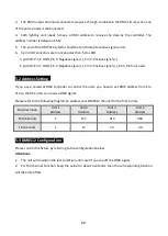
Please refer to the following diagram to address your DMX512 channel for the first 4 units.
Channel mode
Unit 1
Address
Unit 2
Address
Unit 3
Address
Unit 4
Address
156 channels
1
157
313
469
16 channels
1
17
33
49
5.3 DMX512 Configuration
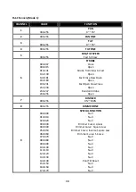
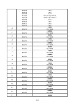
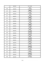
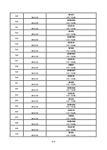
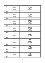
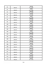
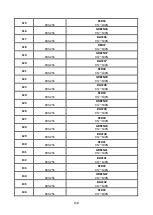
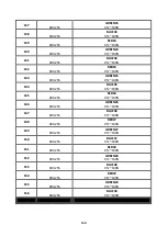
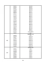
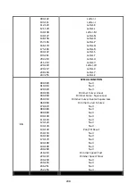
Please control the fixture by referring to the configurations below
Attentions:
1. The unit will maintain the last condition until reset if you cut-off the DMX signal.
2. For the channel Function, keep the value for about 3 seconds, then the corresponding function
will take into effect.
Summary of Contents for BIG BANG
Page 1: ......


