


47
8.9 SETTING THE LASER OFFSET IN SOFTWARE
The horizontal offset of the Laser from the centerline of the Pickup screws is adjustable in the software. The actual
value measured and recorded in the above section 8.8 was measured to the closest side of the Picking Head
horizontal bar. It will be necessary to add 1 ¼” to this measurement to correspond to the center of the picking
screws. The resulting value must be recorded correctly in software to allow the Pickup screws to land on the center
of the board.
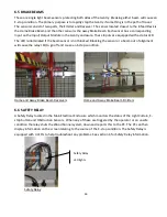
8.10 GANTRY BRAKE
DANGER
- Do Not attempt to take the brake chamber apart. Never loosen either of the band clamps on the brake
chamber. The brake chamber contains a large spring which is compressed and could cause severe injury or death to
anyone servicing the brake system. Replace the entire brake chamber as a unit if service is required.
To Remove the Brake Chamber:
DANGER
- Do Not attempt to remove the brake chamber from the Gantry without caging the spring as outlined
below. Failure to comply may result in severe injury or death.
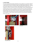
Follow all safety precautions found in this manual and on the brake chamber.
Disconnect the airline between the brake and the valve located on top of the gantry cross member.
Release Tool & Airline Location
Install washer and tighten nuts as shown
Remove brake release tool from its storage area located on the side of the brake. Install washer and tighten
two nuts together as shown.
Brake Airline
Release Tool
Summary of Contents for Wood Runner
Page 5: ...5 ...
Page 36: ...36 ...
Page 37: ...37 ...
Page 54: ...54 ...
Page 55: ...55 10 DETAILED PARTS IDENTIFICATION WOOD RUNNER 10 1 RUNWAY ASSEMBLY ...
Page 58: ...58 10 3 RUNWAY DRIVE ASSEMBLY ...
Page 61: ...61 10 5 GANTRY ASSEMBLY ...
Page 62: ...62 GANTRY ASSEMBLY ...
Page 64: ...64 10 6 PICKING HEAD ASSEMBLY ...
Page 65: ...65 PICKING HEAD ASSEMBLY ...
Page 68: ...68 10 7 ELECTRICAL PANEL ASSEMBLY ...
Page 70: ...70 10 8 GANTRY ENCLOSURE ASSEMBLY ...
Page 72: ...72 10 9 CONSOLE ASSEMBLY ...
Page 73: ...73 CONSOLE ASSEMBLY ...
Page 75: ...75 10 10 AIR SUPPLY ASSEMBLY ...
Page 77: ...77 10 11 GANTRY VALVE ASSEMBLY ...
Page 79: ...79 10 12 GANTRY BRAKE ASSEMBLY ...
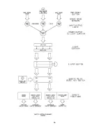
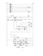
Page 81: ...81 11 ELECTRICAL DIAGRAMS 11 1 SYSTEM OVERVIEW ...
Page 82: ...82 11 2 MAIN ENCLOSURE LOW VOLTAGE ...
Page 83: ...83 11 3 GANTRY WIRING LOW VOLTAGE ...
Page 84: ...84 11 4 I O CHART ...
Page 85: ...85 11 5 INFEED WIRING LOW VOLTAGE ...
Page 86: ...86 11 6 OPERATORS CONSOLE ...
Page 87: ...87 11 7 MAIN ENCLOSURE HIGH VOLTAGE ...
Page 88: ...88 11 8 MAIN ENCLOSURE RECEPTACLE WIRING ...
Page 89: ...89 11 9 SAFETY CIRCUIT LAYOUT ...
Page 90: ...90 11 10 SAFETY CIRCUIT DIAGRAM ...
Page 91: ...91 11 11 BRAKE SENSOR DIAGNOSIS ...
Page 92: ...92 12 PNEUMATIC DIAGRAMS 12 1 SINGLE HEAD GANTRY ...
Page 93: ...93 12 2 DOUBLE HEAD GANTRY ...
Page 94: ...94 12 3 INFEED DECK ...


