


41
7 MAINTENANCE SECTION
Proper maintenance will keep your Wood Runner working efficiently and minimize any downtime.
Maintenance procedures are simple and require very little time.
7.1 DAILY
Inspect all safety guarding to make sure it is in place and fasteners are tight. Repair if
problems are found.
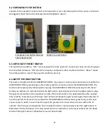
Check the safety system for proper function - blocking the Light Curtain or pushing the E-
stop button should cause the air system to exhaust. Repair any problem found before
operating.
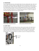
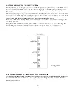
Test the Gantry brake system for proper operation by breaking the Light Curtain beam
when the Gantry is moving. The stopping distance recorded during the stop is displayed on
the manual screen. This distance should be 20” or less. Repair the brake system
immediately if the value is over 20”. Failure to do so may result in machine damage or injury
or death.
Replace pickup screws before starting a work shift.
Check for loose fasteners, wires or airlines.
Listen for air leaks while the system is energized.
Any unusual noises while operating should be investigated immediately.
Remove any debris that has accumulated in the cable carrier channel or on the Runway
wheel path or other parts of the machine.
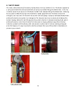
Inspect Gantry Brake Pad for pad material wear. Replace brake pad when worn .
7.2 MONTHLY
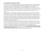
Check for proper drive belt tension and re-tension if necessary.
Tighten any loose fasteners.
Reposition or replace any dangling or chafing wires or airlines.
Inspect Gantry wheels for smooth operation.
Summary of Contents for Wood Runner
Page 5: ...5 ...
Page 36: ...36 ...
Page 37: ...37 ...
Page 54: ...54 ...
Page 55: ...55 10 DETAILED PARTS IDENTIFICATION WOOD RUNNER 10 1 RUNWAY ASSEMBLY ...
Page 58: ...58 10 3 RUNWAY DRIVE ASSEMBLY ...
Page 61: ...61 10 5 GANTRY ASSEMBLY ...
Page 62: ...62 GANTRY ASSEMBLY ...
Page 64: ...64 10 6 PICKING HEAD ASSEMBLY ...
Page 65: ...65 PICKING HEAD ASSEMBLY ...
Page 68: ...68 10 7 ELECTRICAL PANEL ASSEMBLY ...
Page 70: ...70 10 8 GANTRY ENCLOSURE ASSEMBLY ...
Page 72: ...72 10 9 CONSOLE ASSEMBLY ...
Page 73: ...73 CONSOLE ASSEMBLY ...
Page 75: ...75 10 10 AIR SUPPLY ASSEMBLY ...
Page 77: ...77 10 11 GANTRY VALVE ASSEMBLY ...
Page 79: ...79 10 12 GANTRY BRAKE ASSEMBLY ...
Page 81: ...81 11 ELECTRICAL DIAGRAMS 11 1 SYSTEM OVERVIEW ...
Page 82: ...82 11 2 MAIN ENCLOSURE LOW VOLTAGE ...
Page 83: ...83 11 3 GANTRY WIRING LOW VOLTAGE ...
Page 84: ...84 11 4 I O CHART ...
Page 85: ...85 11 5 INFEED WIRING LOW VOLTAGE ...
Page 86: ...86 11 6 OPERATORS CONSOLE ...
Page 87: ...87 11 7 MAIN ENCLOSURE HIGH VOLTAGE ...
Page 88: ...88 11 8 MAIN ENCLOSURE RECEPTACLE WIRING ...
Page 89: ...89 11 9 SAFETY CIRCUIT LAYOUT ...
Page 90: ...90 11 10 SAFETY CIRCUIT DIAGRAM ...
Page 91: ...91 11 11 BRAKE SENSOR DIAGNOSIS ...
Page 92: ...92 12 PNEUMATIC DIAGRAMS 12 1 SINGLE HEAD GANTRY ...
Page 93: ...93 12 2 DOUBLE HEAD GANTRY ...
Page 94: ...94 12 3 INFEED DECK ...


