


30
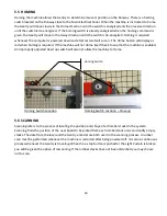
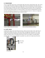
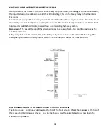
5.5 HOMING
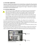
Homing the machine allows the Gantry to determine its exact position on the Runway. There is a homing
switch located on the Runway close to the Main Electrical Panel. When the machine is instructed to home
the Gantry will move slowly in the Home direction until the switch is energized and then reverse direction
until the switch is de-energized. If the homing switch is already energized when the homing command is
given, the Gantry will move in the Away direction until the switch is de-energized. Homing is required
whenever the computer is powered down and after certain faults occur. The Home button will display as
red when homing is required. If the machine will not Home itself check to see that the machine is enabled.
An improperly adjusted Head up switch will also not allow the machine to Home.
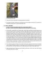
Homing Switch Location
Homing Switch Location – Close up
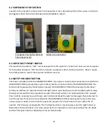
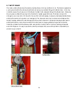
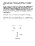
5.6 SCANNING
Scanning refers to the process of locating the position and shape of all lumber stacks in the system.
Scanning finds the position of the next board to be picked from each lumber stack and can identify empty
stacks. The data from the laser and the Gantry encoder are both used in the scanning process. A lumber
scan must be performed whenever the machine is restarted after being powered off. It is also a continuous
process whenever the Gantry is traveling. When the e-stop button is pushed or the Light Curtain is broken
you will be given the option of rescanning. If the lumber stacks have not been disturbed you may choose
not to scan.
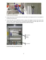
Homing Switch
Summary of Contents for Wood Runner
Page 5: ...5 ...
Page 36: ...36 ...
Page 37: ...37 ...
Page 54: ...54 ...
Page 55: ...55 10 DETAILED PARTS IDENTIFICATION WOOD RUNNER 10 1 RUNWAY ASSEMBLY ...
Page 58: ...58 10 3 RUNWAY DRIVE ASSEMBLY ...
Page 61: ...61 10 5 GANTRY ASSEMBLY ...
Page 62: ...62 GANTRY ASSEMBLY ...
Page 64: ...64 10 6 PICKING HEAD ASSEMBLY ...
Page 65: ...65 PICKING HEAD ASSEMBLY ...
Page 68: ...68 10 7 ELECTRICAL PANEL ASSEMBLY ...
Page 70: ...70 10 8 GANTRY ENCLOSURE ASSEMBLY ...
Page 72: ...72 10 9 CONSOLE ASSEMBLY ...
Page 73: ...73 CONSOLE ASSEMBLY ...
Page 75: ...75 10 10 AIR SUPPLY ASSEMBLY ...
Page 77: ...77 10 11 GANTRY VALVE ASSEMBLY ...
Page 79: ...79 10 12 GANTRY BRAKE ASSEMBLY ...
Page 81: ...81 11 ELECTRICAL DIAGRAMS 11 1 SYSTEM OVERVIEW ...
Page 82: ...82 11 2 MAIN ENCLOSURE LOW VOLTAGE ...
Page 83: ...83 11 3 GANTRY WIRING LOW VOLTAGE ...
Page 84: ...84 11 4 I O CHART ...
Page 85: ...85 11 5 INFEED WIRING LOW VOLTAGE ...
Page 86: ...86 11 6 OPERATORS CONSOLE ...
Page 87: ...87 11 7 MAIN ENCLOSURE HIGH VOLTAGE ...
Page 88: ...88 11 8 MAIN ENCLOSURE RECEPTACLE WIRING ...
Page 89: ...89 11 9 SAFETY CIRCUIT LAYOUT ...
Page 90: ...90 11 10 SAFETY CIRCUIT DIAGRAM ...
Page 91: ...91 11 11 BRAKE SENSOR DIAGNOSIS ...
Page 92: ...92 12 PNEUMATIC DIAGRAMS 12 1 SINGLE HEAD GANTRY ...
Page 93: ...93 12 2 DOUBLE HEAD GANTRY ...
Page 94: ...94 12 3 INFEED DECK ...


