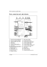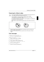
Ports, connectors and switch blocks
A26361-K522-Z122-3-7419
English - 7
i
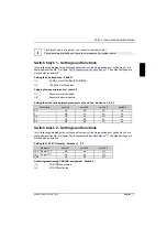
The blackened pin of a jumper or a connector represents pin 1
The connectors marked do not have to be present on the system board.
Switch block 1 - Settings and functions
In the following paragraphs the settings and functions of the single switches of switch block 1 are
explained (position No. 5 in figure "
Ports, connectors and switch blocks
"). The default settings are
marked with an asterisk *.
Setting the bus frequency - Switch 1
On*
66 MHz Front Side Bus (CPU/DIMM)
Off
100 MHz Front Side Bus
Skipping the password query - switch 2
On
Password query enabled
Off*
Password query disabled
Setting the clock ratio between processor core and bus - Switches 3, 4, 5, 6
Clock ratio
switch 3
switch 4
switch 5
switch 6
3,5
on
off
off
on
4
off
on
on
on
4,5
off
on
off
on
5
off
off
on
on
5,5
off
off
off
on
Switch block 2 - Settings and functions
In the following paragraphs the settings and functions of the single switches of switch block 2 are
explained (position No. 9 in figure "
Ports, connectors and switch blocks
"). The default settings are
marked with an asterisk *.
Setting the CRT/LCD display - Switches 1, 2, 3
Indicator
switch 1
switch 2
switch 3
13.3 " Super TFT
off
on
off
14,1 " Super TFT
on
on
off
CRT
off
off
off
Activating/deactivating VGA-IRQ assignment - Switch 4
On*
VGA-IRQ deactivated
Off
VGA-IRQ activated

