background image

1-10

General Description

1.5. Extensa 67x Series Specifications

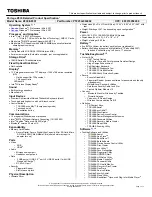
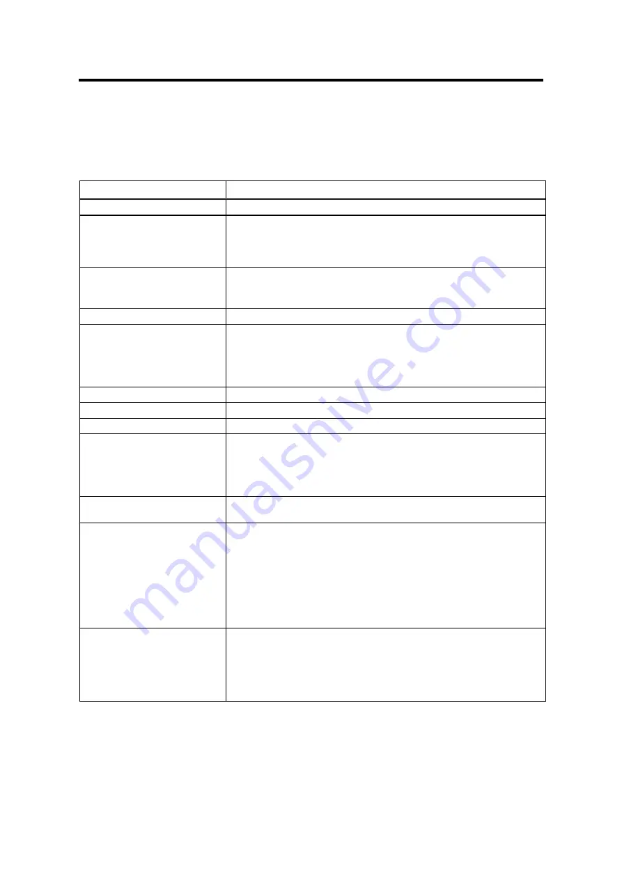
General specifications for the Extensa 67x Series Notebooks are provided in Table 1-5.

Table 1-5

Specifications

Characteristic

Model 670

CPU

Pentium P54CSLM, 133 MHz; 3.1 Volt,

Internal Hard Disk Drive

Disk Storage Capacity
Average access time
Throughput

1.6 GB, 2.1 GB
12 ms or less
11+ Million I/O's per second

DRAM Memory

Size
Maximum Expansion Size

16 MB DRAM, 60-ns, EDO-type
80 MB

Flash ROM

256 KB

FDD

Disk Storage Capacity:
Disk Size
Drive Height
Mode

Media Bay Modular

1.44 MB
3.5-inch disk
12.5 mm
Choice of  720 KB/1.2 MB or 1.44 MB

CD-ROM Drive

Media Bay

LCD Display

12.1-inch DSTN SVGA or 12.1-inch TFT SVGA

Software

Windows 95, Windows NT, or Windows for Workgroups 3.11

Internal Keyboard

Numeric Keypad
Key Travel
Localization Features
Key Spacing

84/85-Key, PS/2 and AT-Compatible

Embedded
3 mm
All major International Language Configurations
19 mm

Built-in Mouse Device

Touchpad built-in to the base of the keyboard (select buttons just below
Touchpad)

Video Subsystem

LCD Aspect Ratio
Emulations
Video Memory Size
Video Bus
LCD Resolution
LCD Characters/Line
LCD Lines/Screen
LCD Brightness Control

1-1
SVGA
2 MByte
32 bits
640x480 pixels bit-mapped at 16.77 million colors; 600x800 at 65K colors
80
25
Function hot key brightness and contrast control and SimulSCAN control

External CRT Monitor Interface

Connector Type
Monitors Supported

15-Pin, female, D-type connector
640 x 480 with 16.7 million colors on CRT
800 x 600 with 16.7 million colors on CRT
1024 x 768 with up to 64K colors on CRT
1280 x 1024 with 256 colors on CRT (interlaced)

Summary of Contents for Extensa 670

Page 1: ...Extensa 670 Extensa 670 Service Guide PART NO 49 47010 001 DOC NO SG248 9708A PRINTED IN TAIWAN ...

Page 2: ...licensed as is Should the programs prove defective following their purchase the buyer and not Acer Incorporated its distributor or its dealer assumes the entire cost of all necessary servicing repair and any incidental or consequential damages resulting from any defect in the software Further Acer Incorporated reserves the right to revise this publication and make changes from time to time in the ...

Page 3: ...ons Chapter 2 Installation This chapter contains unpacking and preparation for use instructions for the system Chapter 3 Operating Instructions This chapter contains a summary of notebook operating procedures useful for maintenance operations Chapter 4 Theory of Operation This chapter contains a general block diagram theory of operation description and major chips introductions Chapter 5 Troublesh...

Page 4: ...iled information on the audio controller NS87336VJG Data Sheet contains detailed information on the super I O controller TI1130 Data Sheet contains detailed information on the PCMCIA controller PCI0643 Data Sheets contain detailed information on the CMD PCI IDE controller T62 045 C 00 Data Sheets contain detailed information on the charger board component DAC 07B008 Data Sheets contain detailed in...

Page 5: ... the keyboard NOTE Gives bits and pieces of additional information related to the current topic WARNING Alerts you to any damage that might result from doing or not doing specific actions CAUTION Gives precautionary measures to avoid possible hardware or software problems IMPORTANT Reminds you to do specific actions relevant to the accomplishment of procedures TIP Tells how to accomplish a procedu...

Page 6: ...Test Features 1 9 1 4 1 Power On Self Test 1 9 1 5 Extensa 67x Series Specifications 1 10 1 6 Regulatory Agency Approvals 1 12 Chapter 2 Installation 2 1 Introduction 2 1 2 2 Unpacking Instructions 2 1 2 3 Installing Internal Notebook Options 2 2 2 3 1 Installing Main Memory Expansion Optional 2 2 2 3 2 Setting up the Software 2 3 2 4 Installing External Options 2 4 2 4 1 Installing PCMCIA Options...

Page 7: ... 3 1 3 2 Controls Indicators 3 1 3 2 1 Power On Off Switch 3 1 3 2 2 Notebook LEDs 3 1 Chapter 4 Theory of Operation 4 1 Introduction 4 1 4 2 Notebook Functional Overview 4 1 4 2 1 System Processor 4 1 4 2 2 Memory Subsystem 4 2 4 2 3 Video Subsystem 4 2 4 2 4 Sound Subsystem 4 2 4 2 5 Keyboard Subsystem 4 3 4 2 6 Hard Disk Drive Subsystem 4 3 4 2 7 Floppy Disk Drive Subsystem 4 3 4 2 8 Power Subs...

Page 8: ...cedures 5 2 5 3 1 Troubleshooting a Power Supply Problem 5 2 5 3 2 Troubleshooting a Display Problem 5 2 5 3 3 Fault Isolation Using Self Test 5 3 5 3 4 PCMCIA Modem Problems 5 7 Chapter 6 Field Service 6 1 Introduction 6 1 6 2 Preventive Maintenance 6 1 6 2 1 Cleaning the Computer 6 1 6 2 2 Handling the Computer 6 1 6 2 3 Handling the Computer Battery Pack 6 2 6 2 4 Password Caution 6 2 6 3 Requi...

Page 9: ...an Assembly 6 15 6 5 13 Removing Replacing the LED Board 6 16 6 5 14 Removing Replacing Inside Frame Assy 6 16 6 5 15 Removing Replacing the Battery Board 6 17 6 5 16 Removing Replacing the Charger Board 6 18 6 5 17 Removing Replacing the Motherboard and Keyboard Connection Board Assemblies 6 19 6 5 18 Removing Replacing the PCMCIA Connector Module 6 20 6 5 19 Removing Replacing the Touchpad Assem...

Page 10: ...k Diagram 4 18 4 12 NS87336VJG Chip Pinouts 4 21 4 13 NS87336VJG Chip Simplified Block Diagram 4 22 4 14 ES1878 Chip Pinouts 4 23 6 1 Removing Installing Cables with Locking Type Connectors 6 3 6 2 Battery Removal Replacement 6 4 6 3 Installing Removing PCMCIA Options 6 5 6 4 Removing the HDD Bay Cover 6 6 6 5 Removing Replacing the Hard Disk Drive Module 6 6 6 6 Removing the Display Hinge Covers ...

Page 11: ...ly 6 16 6 19 Removing Replacing the Battery Board 6 17 6 20 Removing Replacing the Charger Board Assembly 6 18 6 21 Detaching Motherboard from Inside Frame Assembly 6 19 6 22 Removing Replacing the PCMCIA Module 6 20 6 23 Removing Replacing the Touchpad Assembly 6 21 6 24 Display Unit Disassembly 6 22 ...

Page 12: ...ing System Environments 1 6 1 3 External Ports 1 7 1 4 Expansion Features Summary 1 7 1 5 Specifications 1 10 3 1 Indicators 3 2 3 2 Summary of Notebook Hot Key Sequences 3 2 4 1 Major Chips List 4 4 5 1 Display Troubleshooting Guide 5 2 5 2 Self Test Error Messages 5 3 5 3 Self Test Beep Messages 5 5 ...

Page 13: ...neral overview of the Extensa 67x Series describes the standard and optional features and identifies the major assemblies and subassemblies This chapter also contains detailed functional and environmental specifications for the Extensa 67x Series Notebook Computers Figure 1 1 Extensa 67x Series Notebook Computers ...

Page 14: ... JPN US 110v English K Korea US US 110v English L Latin AM SPN US 110v Multi language M Dutch US EUR 220v Multi language N Norway NOR EUR 220v Multi language P Portugal PORT EUR 220v Multi language Q Australia US AUS 250v UK 250v English R Reserved S Spain SPN EUR 220v Multi language T Reserved U UK UK UK 250v Multi language V Reserved W Sweden SWD EUR 220v Multi language X Sws Ger GER EUR 220v Mu...

Page 15: ... 1 Feature Comparison for 65x 67x Series Notebooks Feature 65x Series 67x Series CPU 133 MHz Pentium 150 166 MHz Pentium with MMX Technology Standard Onboard Memory 16 MB 16 MB Maximum Expandable Memory 80 MB 80 MB HDD 1 3 GB or 1 6 GB 1 6 GB or 2 1 GB LCD Display Type DSTN or TFT DSTN or TFT new 12 1 inch DSTN and TFT LCDs Video Memory 2 MB 2 MB Infrared Port 4 Mb s FIR 4 Mb s FIR Internal Microp...

Page 16: ...pin serial port for connecting external devices such as a modem or mouse Simultaneous display with external CRT One Type III or two Type II I Cardbus PC Card slots lower slot accepts Zoomed Video port enabled PC cards Parallel port with EPP and ECP for connecting to a printer or the floppy disk drive module 8 MB 16 MB and 32 MB EDO 64 bit type small outline dual inline memory module soDIMM upgrade...

Page 17: ...lors are supported 1 3 1 3 Display Hot Key Sequences The display mode of operation LCD only Simultaneous LCD and external CRT and external CRT only modes is keyboard selectable using the following hot key sequences Fn Up Arrow and Fn Down Arrow control LCD screen brightness higher brightness setting uses more battery energy Fn Right Arrow lightens the LCD screen contrast Fn Left Arrow darkens the ...

Page 18: ...d Power Management multimedia options and choice of wallpaper to customize different computer resources variety of device drivers including C T 65550 ESS 1878 Sound Device Drivers PC Card Bus Socket Services and Card Services Device Drivers TranXit Communication Utility for parallel serial and FIR IrDA Windows DOS 6 22 This environment has some limitations in the Plug and Play area includes utilit...

Page 19: ...ned with a variety of expansion features that permit substantial functionality and performance upgrades over the life of the product The expansion capabilities built into the notebook are summarized in Table 1 4 and described in greater detail in the following paragraphs Table 1 4 Expansion Features Summary Expansion Feature Description CD ROM Drive Reads from Audio CD Photo CD or CD ROM 3 5 inch ...

Page 20: ...1 8 General Description PCMCIA Card options install on the left side of the notebook Figure 1 5 and are removed using the PCMCIA Release Buttons Figure 1 5 Installing PCMCIA Card Options ...

Page 21: ...n a BIOS resident Power On Self Test POST that automatically performs a test of memory and all major circuits each time the computer is powered up In the event of a failure the computer displays a descriptive error message and issues a series of coded beeps in case the display subsystem is not functioning If self test completes normally the computer displays the amount of memory tested loads the O...

Page 22: ...NT or Windows for Workgroups 3 11 Internal Keyboard Numeric Keypad Key Travel Localization Features Key Spacing 84 85 Key PS 2 and AT Compatible Embedded 3 mm All major International Language Configurations 19 mm Built in Mouse Device Touchpad built in to the base of the keyboard select buttons just below Touchpad Video Subsystem LCD Aspect Ratio Emulations Video Memory Size Video Bus LCD Resoluti...

Page 23: ...1200 2400 4800 9600 19200 Odd even mark space Data check odd even READY BUSY DC1 DC3 7 or 8 bit Yes COM1 IRQ4 3F8h COM2 IRQ3 2F8h COM3 IRQ4 3E8h COM4 IRQ4 2E8h Disable Parallel Port Connector Type FDD Support Selectable Parallel Port BIOS Setup EPP ECP Bidirectional 25 Pin DB 25 Connector Yes Hot Pluggable Auto Detection if BIOS Setup is set to 1 44 MB LPT 1 IRQ5 278h LPT 2 IRQ7 378h Disable Fast ...

Page 24: ...UL Standard 1950 safety Canadian Standards Association CSA Standard 950 or CUL safety FCC CFR 47 Part 15 Subpart B FCC Level B Emissions Canadian Department of Communications DOC ICES Class B Emissions VDE EN60950 Safety EN 50082 1 Immunity ESD RFI EFT and Surge EN 50081 1 Emissions RFI EMI Harmonics and Flicker Approval Marks UL CUL VDE FCC ICES and CE ...

Page 25: ...talling Battery Packs Installing Desktop Devices Installing the AC Adapter Checking Out the System Configuring the System Making Backups of System Software Loading Application Software 2 2 Unpacking Instructions Unpack the computer using the following instructions 1 Carefully cut the tape that seals the top flap of the shipping carton 2 Remove the computer and the accessories Carton from the main ...

Page 26: ...t or ankle grounding straps and grounded working mats When moving or storing items use the anti static bags supplied with the items Figure 2 1 Memory Expansion Removal Replacement 1 Ensure that the notebook is powered off and the AC adapter disconnected from the AC outlet Also ensure that the battery is out of the unit 2 Disconnect any peripheral device interface cables from the external interface...

Page 27: ...t run the PHDISK utility in order for the Save To Disk or 0V Suspend functions to operate correctly 2 3 2 Setting up the Software After installing expansion memory perform the following procedure 1 Run PHDISK In Windows 95 1 From the Taskbar select Start then Shut Down 2 Select the Restart the Computer in MS DOS mode option 3 Click on Yes 4 Type PHDISK C F at the DOS prompt In Windows for Workgrou...

Page 28: ...ed with the PCMCIA option card s 2 Hold the card at the end opposite the connector pins with the label side up Insert the card into an unused slot on the left side of the Notebook 3 If the option requires external cabling e g Modem option connect external cabling at this time Note After installation of a PCMCIA option card Windows 95 displays the New Hardware Found dialog box to help you configure...

Page 29: ...2 5 1 Installing Ext Keyboard Mouse Numeric Keypad A PS 2 compatible keyboard mouse or an optional PS 2 compatible numeric keypad may be installed on the notebook via the mouse connector on the left rear port as shown in Figure 2 3 Figure 2 3 PS 2 Port Pinouts ...

Page 30: ...rallel printer port The connector pinouts and connector location are shown in Figure 2 4 When used with a special cable an external floppy disk drive may also be attached to the notebook via the parallel port When a floppy disk drive is connected to the parallel port the floppy disk drive in the Modular Bay is disabled if present Figure 2 4 Parallel Port Pinouts ...

Page 31: ...al ports are used to interconnect such devices as External Modem Serial Mouse Serial Printer Any device that uses an RS 232 interface Caution Never connect a parallel device to a serial port or a serial device to a parallel port or video port this may cause damage to the notebook and or external device If you are uncertain of what type connector the external device has refer to the technical manua...

Page 32: ...stall an external monitor 1 Turn off power to both the notebook and monitor 2 Connect the 15 pin external VGA cable from the monitor to the VGA connector on the notebook computer refer to Figure 2 6 3 Power up the notebook computer first then turn on power to the monitor 4 Setup the notebook display mode for LCD only simultaneous LCD and CRT or CRT only using the BIOS setup utility or hotkey see P...

Page 33: ...k 1 Unpack the Kensington Lock Kit 2 Secure the loop end of the lock to a permanent fixture located such that the notebook can be installed in a desired location 3 Insert the lock into the slot on the left side of the computer 4 Rotate the key to its locked position and remove the key This completes the options installation subsection ...

Page 34: ...r of the unit as shown in Figure 2 7 2 Slide the battery compartment door out slightly and then swing the door outward as shown in Figure 2 7 3 If changing batteries grasp the loop attached to the battery and pull the battery out of the compartment 4 Look for label THIS SIDE UP and insert the battery with label up until it snaps in place then close the battery compartment door Figure 2 7 Battery P...

Page 35: ... other adapters can damage the unit 1 Remove the AC adapter from the packaging Connect the round coaxial connector supplied with the notebook to the DC IN power receptacle on the left rear of the notebook as shown in Figure 2 8 a 2 Connect the female side of the AC power cord to the AC adapter b and connect the male end to a grounded AC outlet c Figure 2 8 Installing the AC Adapter ...

Page 36: ...sion of self test the computer automatically loads its operating system and windows environment If self test fails to complete and an error message is displayed try powering down the computer for a couple of minutes and turning power back on to repeat self test If the error message persists refer to Chapter 5 for troubleshooting information 2 9 Making Backups of System Software Immediately after c...

Page 37: ...ndicators is provided in the following paragraphs Num Lock LED Caps Lock LED Battery Charging LED Disk Media LED Power Button Standby Mode Indicator Power Battery Low Indicator Figure 3 1 67x Operating Controls and Indicators 3 2 1 Power On Off Switch The notebook contains an alternate action power button located on the right side of the notebook as shown in Figure 3 1 On the first button depressi...

Page 38: ...ery or the battery is fully charged Caps Lock Lights when the caps lock function is toggled ON using the Caps Lock key Num Lock Lights when the embedded numeric keypad is toggled ON using the Num Lock hot key Fn F7 3 2 2 1 Hot Key Sequences Table 3 2 contains a summary of hot key sequences useful when performing maintenance operations Table 3 2 Summary of Notebook Hot Key Sequences Function Key Se...

Page 39: ...disable the internal keypad Fn T Toggle Scroll Lock function on off Fn F6 Bring up the setup screen anytime Fn F1 or Ctrl Alt F1 Warm boot Ctrl Alt Del Start Windows logo key Activate next taskbar button Windows logo key Tab Explore the computer Windows logo key E Find files Windows logo key F Minimize all Windows logo key M Display run dialog box Windows logo key R Display the application s conte...

Page 40: ...hpad assembly and on the Motherboard Assembly Hard Disk Drive Subsystem implemented on the Motherboard Assembly and the Hard Disk Drive Assembly Floppy Disk Drive Subsystem implemented on the Motherboard and Floppy Disk Drive Assembly Power Subsystem implemented on the Charger Board Inverter Board battery packs and AC adapter 4 2 1 System Processor The System Processor function for the notebook is...

Page 41: ... setup routine When the Shadow ROM is enabled BIOS is copied into 32 bit high speed memory system 4 2 3 Video Subsystem The video subsystem is implemented on the Motherboard Assemblies The notebook contains a built in 12 1 inch LCD and features simultaneous LCD and external VGA display The video subsystem includes a 2 MB DRAM memory 32 bit DRAM bus and separate display and memory clocks An additio...

Page 42: ...and the hard disk drive installed in the media bay implement power savings features From the CMOS setup routine an automatic power down mode can be selected which enables the drive to turn off its motor after a specified period of inactivity Additional Sleep modes can direct additional power savings during inactive periods by powering down the control circuitry 4 2 7 Floppy Disk Drive Subsystem Th...

Page 43: ... for the Extensa Series Notebooks 4 3 1 Major Components Table 4 1 shows a listing the of the major components used in the Extensa Series Notebooks Table 4 1 Major Chips List Component Vendor Description M1521 Acer PCI cache and memory controller Host PCI Bridge M1523 Acer System controller chip PCI ISA Bridge M6377 Acer Power management controller 65550 C T Chips Technology Video controller TI113...

Page 44: ...mainder of this chapter provides a detailed description of the major chips used in the Extensa Notebooks 586 CPU SRAM M1521 BGA DRAM HDD M1523 UMA Graphic controller IDE Master Aladdin III System Block Diagram CD CPU Bus PCI Bus ISA Bus USB connector Figure 4 1 Extensa 670 System Architecture Diagram ...

Page 45: ...a most up to date system architecture including the UMA ECC PBSRAM SDRAM BEDO and multi bus with highly efficient deep FIFO between the buses such as the HOST PCI ISA dedicated IDE bus The M1521 provides a complete integrated solution for the system controller and data path components in a Pentium based system It provides a 64 bit CPU bus interface 32 bit PCI bus interface 64 72 DRAM data bus with...

Page 46: ...Service Guide 4 7 Figure 4 2 M1521 Pin Assignments ...

Page 47: ...ompatible CPUs It implements programmable hardware events software event and external switches for suspend turbo ring in The M1523 provides CPU clock control STPCLKJ The STPCLKJ can be active low or inactive high in turn by throttling control A simplified block diagram of the M1523 chip is shown in Figure 4 3 and the associated pinouts are provided in Figure 4 4 M1523 Block Diagram DATA Buffer Con...

Page 48: ...VDD BAT RTC32KII RTC32KI PWG LA20 LA19 IRQ15 LA18 IRQ14 LA17 MEMRJ DREQ0 Vss MEMWJ DACK5J SD8 DREQ5 SD9 DACK6J SD10 DREQ6 SD11 DACK7J SD12 DREQ7 SD13 VDD SD14 SD15 OSC14M SIRQI SIRQII USBCLK DACK0J DACK1J CPURST SMIJ STPCLKJ Vss 1 2 3 4 5 6 7 8 9 10 11 12 13 14 15 16 17 18 19 20 21 22 23 24 25 26 27 28 29 30 31 32 33 34 35 36 37 38 39 40 41 42 43 44 45 46 47 48 49 50 51 52 156 155 154 153 152 151 ...

Page 49: ...ty monitoring including video hard disk floppy disk serial port keyboard parallel port two programmable I O groups activity monitor each group contains 16 8 I O addresses one predefined I O group activity monitor Multiple external wake up events from DOZE and SLEEP states External push button RTC alarm Two levels battery warning monitor AC power monitoring to disable PMU function A simplified bloc...

Page 50: ...Guide 4 11 ACTIVITY MONITOR EL TIMER PROGRAMABLE APM TIMER x 2 BATTERY MONITOR GPIO SMI HANDLER STATE CONTROLLER WAKEUP EVENT HANDLER BUS INTERF ACE Timebase OTHER Figure 4 5 M6377 Chip Simplified Block Diagram ...

Page 51: ...4 12 Theory of Operation Figure 4 6 M6377 Chip Pinouts ...

Page 52: ...ouble buffered fro smoothing and to prevent image tearing The display system can independently place either RGB or YUV data from anywhere in display memory into an onscreen window which can be any size and located at any pixel boundary YUV data is converted to RGB on the fly on output Non rectangular windows are supported via color keying The data can be functionally zoomed on output up to 8x to f...

Page 53: ...4 14 Theory of Operation The pin diagram is shown in Figure 4 7 Pin names in parentheses indicate alternate functions Figure 4 7 C T65550 Chip Pinouts ...

Page 54: ...of the C T65550 is shown in Figure 4 8 Memory Controller Scaling Capture 64 bit Graphics Engine YUV to RGB Color Key Zoom Bus Interface Video Capture Port PCI Bus Analog RGB Digital RGB Video Memory Figure 4 8 C T65550 Chip Simplified Block Diagram ...

Page 55: ...ision 2 1 and its PCI interface can act as either a PCI master device or a PCI slave device The PCI bus mastering is initiated during 16 bit PC Card DMA transfers or CardBus PC Card bus mastering cycles All card signals are internally buffered to allow hot insertion and removal without external buffering The PCI1130 internal data path logic allows the host to access 8 16 and 32 bit cards using ful...

Page 56: ...Service Guide 4 17 Figure 4 10 TI1130 Chip PCI to CardBus 32 bit Pinouts ...

Page 57: ...4 18 Theory of Operation A simplified block diagram of the PCMCIA Controller is shown in Figure 4 11 Figure 4 11 TI1130 Chip Simplified Block Diagram ...

Page 58: ...lly IEEE 1284 level 2 compatible The SPP Standard Parallel Port is fully compatible with ISA dand EISA parallel ports In addtion to the SPP EPP Enhanced Parallel Port and ECP Extended Capabilities Port modes are supported by the parallel port A set of configuration registers are provided to control the Plug and Play and other various functions of the PC87336 These registers are accessed using tow ...

Page 59: ...y when 10 bit decoding Full relocation capability no limitation Enhanced Power Management Special configuration registers for power down Enhanced programmable power down FDC command Auto power down and wake up modes 2 special pins for power management Typical current consumption during power down is less than 10 µA Reduced pin leakage current Mixed Voltage support Supports standard 5V operation Su...

Page 60: ...Service Guide 4 21 The pin diagram is shown in Figure 4 12 Figure 4 12 NS87336VJG Chip Pinouts ...

Page 61: ...eral Purpose Registers Power Down Logic IEEEE1284 Parallel Port Hifh Current Driver Floppy Disk Controller with Digital Data Separator Enhabced 8477 I O Ports Control Interrupt Data Handshake Floppy Drive Interface OSC Interrupt and DMA Floppy Drive Interface Interrupt IR Interface Serial Interface Interrupt Serial Interface Config Inputs Figure 4 13 NS87336VJG Chip Simplified Block Diagram ...

Page 62: ... for up to 7 general purpose outputs and 7 general purpose inputs that can be slaved with corresponding pins of ES978 in expansion unit IIS interface to intemal stereo D A for external ZV port or MPEG audio Completely general interrupt mapping including sharing all interrupts GNDD A0 A1 A2 A2 A4 A5 A6 A7 A8 A9 A10 A11 AEN VDDD D0 D1 D2 D3 D4 D5 D6 D7 GNDD SWD Xl VDDD RESET DOCKED IIMCLK llLR IISLC...

Page 63: ...ower is On Press the Shift key to ensure that Notebook is not in Suspend mode Verify if computer is configured to boot from the A Drive or C Drive Check LCD brightness adjustment press Fn Up Arrow keys to increase brightness Ensure that computer is not set for external monitor press Fn F12 to select internal screen Record and attempt to resolve any displayed error messages or error beeps refer to ...

Page 64: ...good appliance e g a lamp to verify that voltage is present If the voltage is ok try replacing the AC adapter Check to see that the battery packs are installed correctly and that the battery charge indicators on the front of the battery packs indicate the batteries are charged try using a new battery pack if batteries are discharged If the AC outlet voltage AC adapter and battery packs test normal...

Page 65: ...lly performs a self test of its central hardware and memory functions During self test which lasts for a few seconds the display shows copyright and version number information Note Some procedures in this paragraph require you to use keystroke sequences such as Ctrl Alt Del To execute a keystroke sequence such as this you must press all three keys simultaneously 5 3 3 1 Self Test Error Messages Up...

Page 66: ...lure This message indicates the self test has detected a stuck key on the keyboard Try the keyboard keys to determine if they appear to be working properly and reboot the computer Note Also ensure that no key is pressed during power up and that no keys are jammed If the self test still fails execute the diagnostics as described in Paragraph 5 4 No boot device available press F1 to retry boot This ...

Page 67: ...t the Setup configuration is correct In general most of the failures are associated with the Motherboard and may require board removal replacement Table 5 3 Self Test Beep Messages Beep Code Port 80h Description None 01h CPU Register Test in Progress 1 1 3 02h CMOS Write Read Failure 1 1 4 03h ROM BIOS Checksum Failure 1 2 1 04h Programmable Interval Timer Failure 1 2 2 05h DMA Initialization Fail...

Page 68: ...ess 3 3 4 2Bh Screen Memory Test Failure 3 4 1 2Ch Screen Initialization Failure 3 4 2 2Dh Screen Retrace Test Failure None 2Eh Search for Video ROM in progress 1 2 2Eh Cirrus Video Chip Failure 1 3 2Eh Cirrus RAM DAC or Video RAM Failure None 30h Screen Believed Operable running with Video ROM None 31h Monochrome Monitor Believed Operable None 32h Color Monitor 40 Column Believed Operable None 33...

Page 69: ...properly check the following items Dialing problem or wrong number Try dialing a number that you have previously dialed successfully Faulty phone line Connect a telephone to the line and listen for a dial tone Software program Check to ensure that you have installed the software correctly ...

Page 70: ...f the liquid crystal display LCD screen has become smeared or dusty clean the screen first with a soft clean lint free cloth and gently wipe the glass If the glass is still smeared use distilled water or a 25 solution of alcohol and distilled water Caution Do not use paper towels to clean the display screen Paper can scratch the display screen matte 6 2 2 Handling the Computer The notebook compute...

Page 71: ...l Always charge the battery pack as soon as possible after a low battery indication 6 2 4 Password Caution The notebook computer can be password protected to prevent unauthorized use However if the password is lost the notebook must be returned to the Acer Incorporated manufacturing facility in Temple Texas U S A to restore access This service is not covered by warranty 6 3 Required Tools and Equi...

Page 72: ...ook Computers Most FRU removal replacement procedures involve connecting and disconnecting cable connectors The Extensa series uses two types of connectors including Locking type connectors use a plastic stick to unlock and lock these type of connectors as shown in Figure 6 1 Non locking connectors Figure 6 1 Removing Installing Cables with Locking Type Connectors ...

Page 73: ... the AC adapter from the computer 2 Unlatch the battery compartment door right front corner of the unit as shown in Figure 6 2 3 Slide the battery compartment door out slightly and then swing the door outwards as shown in Figure 6 2 4 Grasp the loop attached to the battery and pull the battery out of the compartment 5 Insert the replacement battery with THIS SIDE UP label facing upwards until it s...

Page 74: ...e battery pack as described in Paragraph 6 5 1 2 Press the upper card eject button to eject the upper card lower button controls the lower card and use both buttons for Type III devices 3 To replace the PCMCIA device remove any filler cards present and insert the device Reinstall any external cabling required for the device Figure 6 3 Installing Removing PCMCIA Options ...

Page 75: ...the computer over and locate the release tab for the hard disk drive bay cover refer to Figure 6 4 4 While pressing slightly on the release tab Figure 6 4 slide the cover to the right and set aside Figure 6 4 Removing the HDD Bay Cover Figure 6 5 Removing Replacing the Hard Disk Drive Module 5 While lifting upward on the HDD release tab using your fingernails use both finger grip areas Figure 6 5 ...

Page 76: ... notebook to a full 180 degree position as shown in Figure 6 6 3 Slide each of the two display hinge covers out and pull upward to remove from the notebook Figure 6 6 Removing the Display Hinge Covers 4 Pull up on the keyboard as shown in Figure 6 7 and disconnect the Keyboard cable connectors J0102 and J0103 5 If you intend to remove further then disconnect the Touchpad cable connector J0104 Figu...

Page 77: ... the slot locks located on each side of the Expansion Memory Connector to release the DIMM Then pull the memory module out refer to Figure 6 8 6 To replace or install a DIMM module first align the connector edge of the memory module with the key in the connector Insert the edge of the memory module board into the connector using a rocking motion to fully insert the module Push downward on each sid...

Page 78: ...move and replace the Heat Sink Assembly 1 Remove the Keyboard Assembly as described in Paragraph 6 5 4 2 Remove the two screws that secure the heat plate to the housing as shown in Figure 6 9 3 Replacement is the reverse of Steps 1 and 2 Figure 6 9 Removing Replacing the Heat Sink Assembly ...

Page 79: ... Heat Sink Assembly as described in Paragraph 6 5 7 2 Refer to Figure 6 10 Insert a flat blade screwdriver into the opening at the left end of the socket labeled OPEN and push toward the other end of the socket 3 Pull out the CPU and insert the replacement unit Ensure that the CPU is properly keyed before pressing it into the socket 4 Insert a flat bladed screwdriver into the opening at the right ...

Page 80: ...apter as described in Paragraph 6 5 1 2 Unlatch the module by pushing the Module Lock Figure 6 11 toward the unlock icon 3 Grasp the recessed grip area on the module and pull the module straight out 4 Reinstall the module by reversing Step 3 Figure 6 11 Removing Replacing a Module ...

Page 81: ...aph 6 5 1 2 Refer to Figure 6 12 and remove the two screws that secure the display cable to the Motherboard assembly Then unplug display cable J19 Figure 6 12 Unplugging the Display Cable 3 Remove the four display hinge screws Figure 6 13 and separate the Display Assembly from the Base Assembly 4 Installation is the reverse of Steps 1 through 3 Figure 6 13 Removing the Display Hinge Screws ...

Page 82: ...e screws on the bottom that hold the top cover in place unsnap and remove the top cover refer to Figure 6 14 Replacement of the top cover is the reverse of Steps 1 through 3 1 Remove two screws near display hinge screw holes 2 Remove 9 screws from the bottom of the unit 1 circled screw is shorter 3 Unsnap and remove the top cover Figure 6 14 Removing Replacing the Top Cover ...

Page 83: ... Refer to Figure 6 15 and remove the following connectors Left Speaker Cable J4 Internal Microphone Cable J5 Fan Connector J6 Right Speaker Cable J7 Figure 6 15 Unplugging Cables on FIR Audio Board 4 Remove the two screws that secure the FIR Audio Board to the Motherboard and remove the cover plate refer to Figure 6 15 5 Pull up and remove the FIR Audio Board Figure 6 16 6 Replacement is the rever...

Page 84: ...e the cover plate to the FIR Audio Board 3 Remove the two screws holding the fan assembly in place and unplug the fan cable connector J6 from the FIR Audio Board refer to Figure 6 17 4 Remove the Fan Assembly 5 Replacement is the reverse of Steps 1 through 4 Figure 6 17 Internal Assemblies Removal Replacement J17 CN1 Fan Assembly LED Board Assembly LED Board Cable Battery Board Cable Battery Board...

Page 85: ...h 3 6 5 14 Removing Replacing Inside Frame Assy Use the following procedure to separate the inside frame assembly from the base assembly 1 Remove the Top Cover as described in Paragraphs 6 5 10 2 Separate the inside frame assembly from the base assembly as shown in Figure 6 18 Remove three screws that secure the inside frame assembly to the base assembly Separate the inside frame assembly from the...

Page 86: ...d in Paragraph 6 5 10 2 Disconnect the Battery Board Cable from the Main Board refer to Figure 6 17 3 Remove the two screws holding the Battery Board and remove the Battery Board Assembly refer to Figure 6 19 4 Replacement is the reverse of Steps 1 through 3 Figure 6 19 Removing Replacing the Battery Board ...

Page 87: ...graphs 6 5 10 respectively 2 Separate the inside frame assembly from the base assembly as shown in Figure 6 18 3 Turn the unit over and remove the screw holding the Charger Board to the inside of the Frame Assembly Figure 6 20 Remove the Charger Board 4 To reinstall the Charger Board reverse the removal procedure Figure 6 20 Removing Replacing the Charger Board Assembly ...

Page 88: ...plug the Battery Board LED Board Connector as described in paragraph 6 5 12 4 Refer to Paragraph 6 5 16 and remove the Charger Board Assembly 5 Remove the five screws that secure the motherboard to the inside assembly frame Pull up on the Motherboard Assembly to release it from the inside assembly frame refer to Figure 6 21 6 Turn the motherboard over and remove the Keyboard Connection Board Figur...

Page 89: ...move replace the PCMCIA Connector Module 1 Remove the Motherboard Assembly as described in Paragraph 6 5 17 2 Remove the four screws securing the PCMCIA Module to the Motherboard Assembly refer to Figure 6 22 3 Replacement is the reverse of Steps 1 through 3 Figure 6 22 Removing Replacing the PCMCIA Module ...

Page 90: ...Remove the two side screws and remove the metal plate 6 Lift up and remove the Touchpad buttons 7 Lift up and remove the Touchpad 8 Replacement is essentially the reverse of Steps 1 through 7 Remove 1 screw and disconnect J1 Lift up and remove touchpad buttons Lift up and remove touchpad Figure 6 23 Removing Replacing the Touchpad Assembly Caution If the notebook is powered up with the LCD bezel r...

Page 91: ...as described in Paragraph 6 5 1 2 Remove the round LCD bumpers at the top of the display refer to Figure 6 24 3 Remove the left and right screws near the display hinges note that the screw covers are not identical 4 Remove four screws on the Display Bezel Figure 6 24 5 Pull out and remove the Display Bezel Figure 6 24 Display Unit Disassembly LCD Inverter LCD ID Board CN2 ...

Page 92: ...5 22 Removing Replacing the LCD Panel To remove replace the LCD Panel use the following the procedure 1 Remove the Display Bezel as described in Paragraph 6 5 20 2 Slide out and remove the Hinge Cable Cover Figure 6 24 3 Remove four screws on the four sides of the LCD panel Figure 6 24 4 Gently fold back the foil around the LCD and unplug Inverter Cable CN2 5 Remove the three screws that secure th...

Page 93: ... Series Notebook Computers come standard with a 12 1 inch Super VGA Display 1 6 or 2 1 GB Hard Drive and is powered by a 150 or 160 MHz Pentium processor Refer to Chapter 1 for a more detailed description of Extensa 67x Series features A 3 Field Replaceable Units FRUs Note For FRU removal replacement procedures refer to Chapter 6 of this manual As shown in Figure A 1 all members of the Extensa 67x...

Page 94: ...9 071 LCD Panel 12 1 TFT 6 5 22 56 07530 011 Display Back Cover 12 1 6 5 22 Display Bezel for 12 1 DSTN LCD 6 5 20 41 46913 001 Display Bezel for 12 1 TFT LCD 6 5 20 41 47003 001 LCD ID Board for 12 1 DSTN LCD 6 5 21 19 21018 111 LCD ID Board for 12 1 TFT LCD 6 5 21 19 21018 121 LCD Inverter for 12 1 TFT DSTN LCD 6 5 21 19 21026 041 Display Cable Assembly for 12 1 DSTN LCD 6 5 22 50 46915 021 Disp...

Page 95: ...ription Assembly Disassembly Paragraph Part No PC Board Assemblies Motherboard 6 5 17 Audio Baord 6 5 18 55 47002 001 LED Board 6 5 13 55 47003 001 Power Supply Charger Board 6 5 16 05 62045 010 Battery Board W Cable 6 5 15 55 46904 501 Keyboard Connection Board 6 5 17 55 46905 501 Touchpad Assembly 6 5 19 56 17469 011 Button Board Logic w Cable Assembly 6 5 19 50 46912 001 KeyBoard Logic Assembli...

Page 96: ...mbly Japanese 6 5 4 90 46907 00J Cables Internal CD ROM FPC Cable 6 5 8 50 47002 001 Internal CD ROM FPC Cable 6 5 8 50 47003 001 Peripherals FDD 1 44 MB 6 5 8 56 01051 071 HDD 1620 MB 6 5 3 56 02921 021 HDD 2160 MB 6 5 3 56 02941 011 CD ROM Drive 8X 6 5 8 56 10019 011 Covers Doors Buttons Top Cover Assembly 6 5 10 60 47005 001 Memory Expansion Cover 6 5 5 34 46904 011 Left Hinge Cover 6 5 4 42 46...

Page 97: ...DE 12V0 3A RT DS 1200 02 SW3 22 40048 341 BTY LI 3V BR1225 H1A 48MAH BT1 23 20004 071 BUZZER KSS 1201E 2048HZ D12 J13 23 60010 011 CONN CTR SMD ML 32P ST D0 8 J14 20 F0009 032 CONN D SMD 40P RT D0 635 J16 21 A0004 040 CONN D SMD 52P RT D0 635 H11 J15 21 A0006 052 HEAD SMD FML 2R 4P ST D2 4S J9 21 E0004 202 HEAD SMD FML 2R 30P ST D2 4S J8 21 E0004 215 CONN CTR SMD FML 80P ST D0 5 J7 21 F0010 080 SS...

Page 98: ...CD4066BC SO N 14P U10 73 04066 091 IC TRANSCEIVER MAX213ECAI SSOP U36 74 00213 0F9 IC V R PST594CMT SO N 4P U32 74 00594 031 IC OP LM1458 SO N 8P U41 74 01458 011 IC PWR SW TPS2013D SO N 8P U37 38 74 02013 031 IC A R LP2951ACM SO N 8P U40 74 02951 A31 IC INTF SW SI9706DY SO N 8P U39 45 47 74 09706 031 THERMOMETER DS1620 SO N 8P TH1 75 01620 041 RESO 8MHZ CSTC8 00MT CERAMIC X1 82 10009 001 CRYSTAL ...

Page 99: ...ard connector J16 HDD connector J8 Charger connector J14 Keyboard transfer board connector J10 DC DC converter connector J11 PC Card connector J12 Debug card golden finger J7 Display cable connector Password Switch SW1 SW1 ON OFF switch 1 bypass check switch 2 reserved CPU Speed Switch SW2 CPU Core Voltage Switch on DC DC converter SW2 150 MHz 166 MHz 3 1V 2 9V switch 1 ON OFF switch 1 OFF ON swit...

Page 100: ... A 5 Main Board Jumper Options bottom side U1 FIR J4 Left speaker connector SW1 LCD cover switch J5 Internal microphone connector J1 Mic in connector J6 Fan connector J2 Line in connector J7 Right speaker connector J3 Line out connector Figure A 6 FIR Audio Board Jumper Options J18 SW3 U1 SW1 J1 J2 J3 J4 J5 J6 J7 DIMM1 DIMM2 ...

Page 101: ...Service Guide A 9 A 5 Logic Diagrams The remainder of this chapter contains logic diagrams for the Extensa Model 67x Series The following pages 36 sheets contains the logic diagrams for the main board ...

Page 102: ...A 10 Maintenance Data Figure A 7 Main Board Logic Diagrams Sheet 1 of 36 ...

Page 103: ...Service Guide A 11 Figure A 8 Main Board Logic Diagrams Sheet 2 of 36 ...

Page 104: ...A 12 Maintenance Data Figure A 9 Main Board Logic Diagrams Sheet 3 of 36 ...

Page 105: ...Service Guide A 13 Figure A 10 Main Board Logic Diagrams Sheet 4 of 36 ...

Page 106: ...A 14 Maintenance Data Figure A 11 Main Board Logic Diagrams Sheet 5 of 36 ...

Page 107: ...Service Guide A 15 Figure A 12 Main Board Logic Diagrams Sheet 6 of 36 ...

Page 108: ...A 16 Maintenance Data Figure A 13 Main Board Logic Diagrams Sheet 7 of 36 ...

Page 109: ...Service Guide A 17 Figure A 14 Main Board Logic Diagrams Sheet 8 of 36 ...

Page 110: ...A 18 Maintenance Data Figure A 15 Main Board Logic Diagrams Sheet 9 of 36 ...

Page 111: ...Service Guide A 19 Figure A 16 Main Board Logic Diagrams Sheet 10 of 36 ...

Page 112: ...A 20 Maintenance Data Figure A 17 Main Board Logic Diagrams Sheet 11 of 36 ...

Page 113: ...Service Guide A 21 Figure A 18 Main Board Logic Diagrams Sheet 12 of 36 ...

Page 114: ...A 22 Maintenance Data Figure A 19 Main Board Logic Diagrams Sheet 13 of 36 ...

Page 115: ...Service Guide A 23 Figure A 20 Main Board Logic Diagrams Sheet 14 of 36 ...

Page 116: ...A 24 Maintenance Data Figure A 21 Main Board Logic Diagrams Sheet 15 of 36 ...

Page 117: ...Service Guide A 25 Figure A 22 Main Board Logic Diagrams Sheet 16 of 36 ...

Page 118: ...A 26 Maintenance Data Figure A 23 Main Board Logic Diagrams Sheet 17 of 36 ...

Page 119: ...Service Guide A 27 Figure A 24 Main Board Logic Diagrams Sheet 18 of 36 ...

Page 120: ...A 28 Maintenance Data Figure A 25 Main Board Logic Diagrams Sheet 19 of 36 ...

Page 121: ...Service Guide A 29 Figure A 26 Main Board Logic Diagrams Sheet 20 of 36 ...

Page 122: ...A 30 Maintenance Data Figure A 27 Main Board Logic Diagrams Sheet 21 of 36 ...

Page 123: ...Service Guide A 31 Figure A 28 Main Board Logic Diagrams Sheet 22 of 36 ...

Page 124: ...A 32 Maintenance Data Figure A 29 Main Board Logic Diagrams Sheet 23 of 36 ...

Page 125: ...Service Guide A 33 Figure A 30 Main Board Logic Diagrams Sheet 24 of 36 ...

Page 126: ...A 34 Maintenance Data Figure A 31 Main Board Logic Diagrams Sheet 25 of 36 ...

Page 127: ...Service Guide A 35 Figure A 32 Main Board Logic Diagrams Sheet 26 of 36 ...

Page 128: ...A 36 Maintenance Data Figure A 33 Main Board Logic Diagrams Sheet 27 of 36 ...

Page 129: ...Service Guide A 37 Figure A 34 Main Board Logic Diagrams Sheet 28 of 36 ...

Page 130: ...A 38 Maintenance Data Figure A 35 Main Board Logic Diagrams Sheet 29 of 36 ...

Page 131: ...Service Guide A 39 Figure A 36 Main Board Logic Diagrams Sheet 30 of 36 ...

Page 132: ...A 40 Maintenance Data Figure A 37 Main Board Logic Diagrams Sheet 31 of 36 ...

Page 133: ...Service Guide A 41 Figure A 38 Main Board Logic Diagrams Sheet 32 of 36 ...

Page 134: ...A 42 Maintenance Data Figure A 39 Main Board Logic Diagrams Sheet 33 of 36 ...

Page 135: ...Service Guide A 43 Figure A 40 Main Board Logic Diagrams Sheet 34 of 36 ...

Page 136: ...A 44 Maintenance Data Figure A 41 Main Board Logic Diagrams Sheet 35 of 36 ...

Page 137: ...Service Guide A 45 Figure A 42 Main Board Logic Diagrams Sheet 36 of 36 ...

Reviews: