80
Chapter 3
LCD Module Disassembly Process
IMPORTANT:
Cable paths and positioning may not represent the actual model. During the removal and
replacement of components, ensure all available cable channels and clips are used and that the cables are
replaced in the same position.
NOTE:
The product previews seen in the disassembly procedures may not represent the final product color or
configuration.
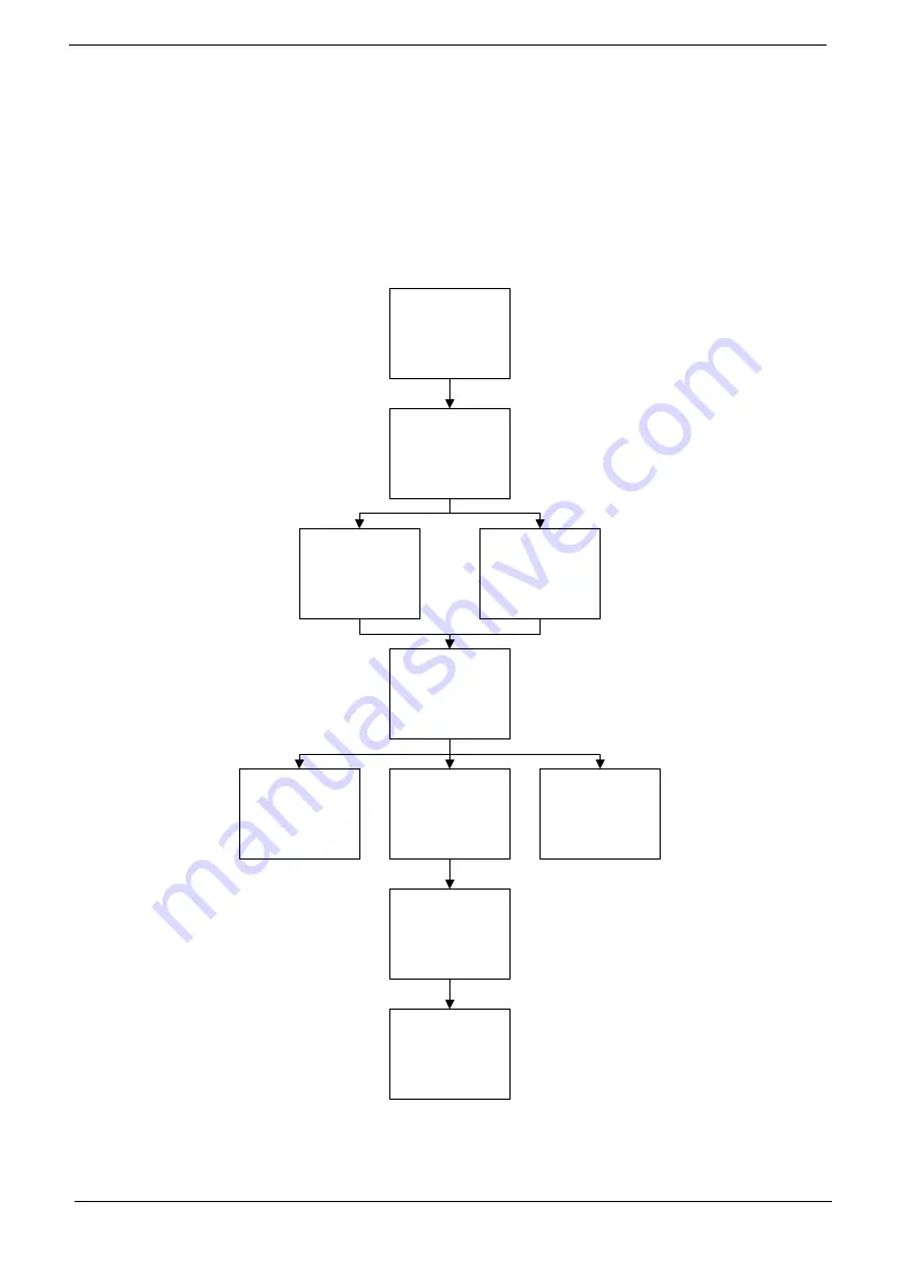
LCD Module Disassembly Flowchart
Remove
LCD Brackets
Remove
Camera Module
Remove
LCD FPC Cable
Remove LCD
Module from Main
Unit before
proceeding
Remove
LCD Panel
Remove
Touchscreen
Board
Remove
Microphone
Remove
LCD Module
Bezel
Remove
Hinges
Remove
Antennas
Summary of Contents for Aspire 1420P Series
Page 6: ...vi...
Page 10: ...x Table of Contents...
Page 13: ...Chapter 1 3 System Block Diagram...
Page 32: ...22 Chapter 1...
Page 48: ...38 Chapter 2...
Page 64: ...54 Chapter 3 4 Unlock the FPC 5 Remove the FPC and keyboard...
Page 66: ...56 Chapter 3 4 Remove the hinge cap 5 Remove the hinge bezel...
Page 70: ...60 Chapter 3 10 Pull the upper cover away...
Page 94: ...84 Chapter 3 7 Pry up the bezel top edge and remove...
Page 119: ...Chapter 3 109 7 Insert the stylus...
Page 148: ...138 Chapter 3 2 Replace the HDD in the bay 3 Adhere the black tape 4 Replace the HDD FPC...
Page 202: ...192 Appendix A...
Page 212: ...202...
Page 215: ...205...
Page 216: ...206...


