


Chapter 5
165
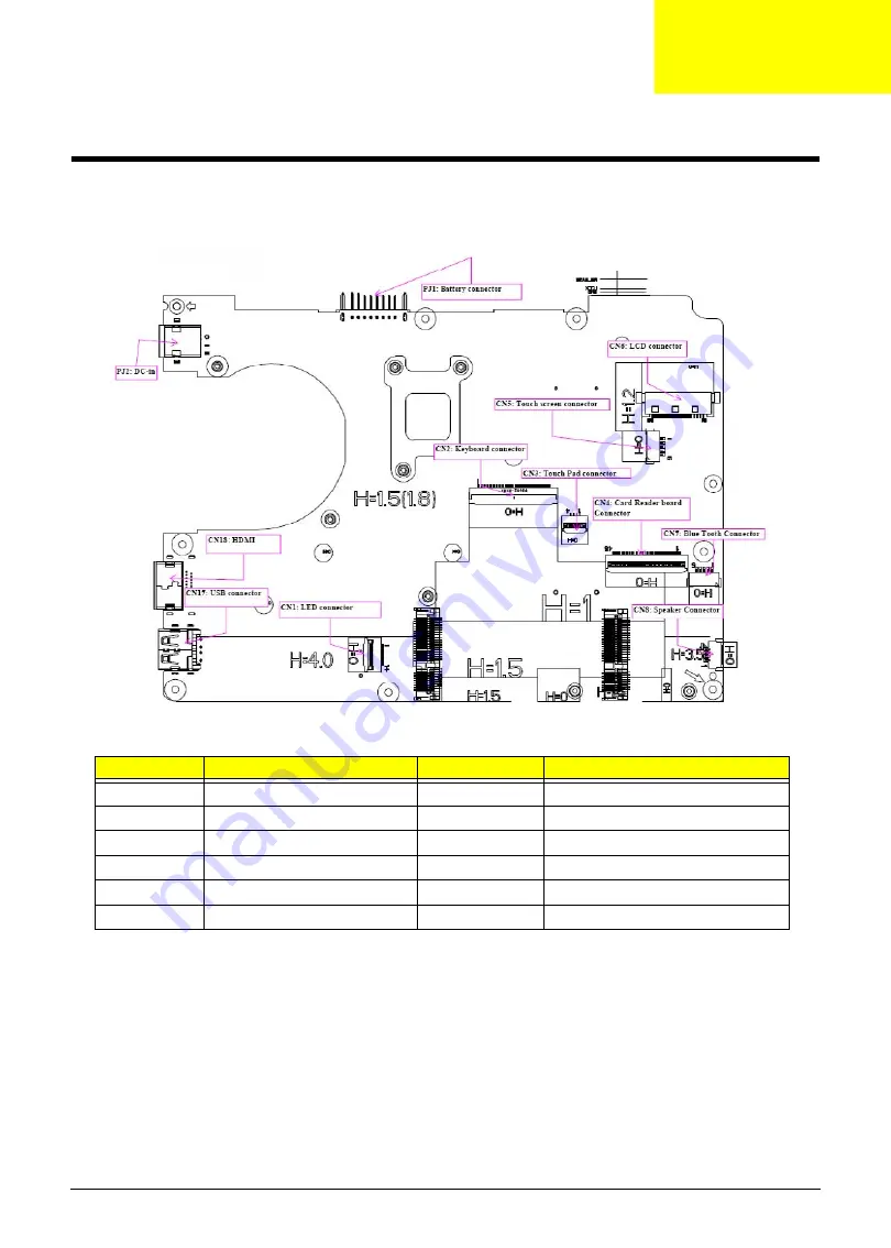
Jumper and Connector Locations
Mainboard Top View
Item
Description
Item
Description
PJ2
DC-in
CN1
LED connector
PJ1
Battery connector
CN17
USB connector
CN6
LCD connector
CN18
HDMI
CN5
Touchscreen connector
CN2
Keyboard connector
CN7
Bluetooth connector
CN3
Touchpad connector
CN8
Speaker connector
CN4
Card reader board connector
Chapter 5
Summary of Contents for Aspire 1420P Series
Page 6: ...vi...
Page 10: ...x Table of Contents...
Page 13: ...Chapter 1 3 System Block Diagram...
Page 32: ...22 Chapter 1...
Page 48: ...38 Chapter 2...
Page 64: ...54 Chapter 3 4 Unlock the FPC 5 Remove the FPC and keyboard...
Page 66: ...56 Chapter 3 4 Remove the hinge cap 5 Remove the hinge bezel...
Page 70: ...60 Chapter 3 10 Pull the upper cover away...
Page 94: ...84 Chapter 3 7 Pry up the bezel top edge and remove...
Page 119: ...Chapter 3 109 7 Insert the stylus...
Page 148: ...138 Chapter 3 2 Replace the HDD in the bay 3 Adhere the black tape 4 Replace the HDD FPC...
Page 202: ...192 Appendix A...
Page 212: ...202...
Page 215: ...205...
Page 216: ...206...


