


Chapter 4
145
No Display Issue
If the
Display
doesn’t work, perform the following actions one at a time to correct the problem. Do not replace
non-defective FRUs:
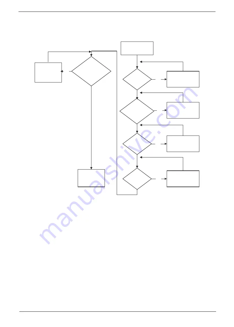
No POST or Video
If the POST or video doesn’t display, perform the following actions one at a time to correct the problem.
1.
Make sure that the internal display is selected. On this notebook model, switching between the internal
display and the external display is done by pressing
Fn+F5
. Reference Product pages for specific model
procedures.
2.
Make sure the computer has power by checking at least one of the following occurs:
•
Fans start up
•
Status LEDs light up
If there is no power, see “Power On Issue” on page 144.
3.
Drain any stored power by removing the power cable and battery and holding down the power button for
10 seconds. Reconnect the power and reboot the computer.
4.
Connect an external monitor to the computer and switch between the internal display and the external
display is by pressing
Fn+F5
(on this model).
If the POST or video appears on the external display, see “LCD Failure” on page 147.
5.
Disconnect power and all external devices including port replicators or docking stations. Remove any
memory cards and CD/DVD discs. Restart the computer.
START
Power On ?
No
Go to No Power
troubleshooting
step
Replace external
DDRAM module
Remove and
replace thermal
module
Replace the
main board
Reconnect
SDRAM Module
LCD Module OK?
Replace LCD
Panel and
Cable
Ext. DDRAM module
connected properly?
Ext. DDRAM
module functional?
CPU Thermal
Module properly
connected?
No
No
No
No
Summary of Contents for Aspire 1420P Series
Page 6: ...vi...
Page 10: ...x Table of Contents...
Page 13: ...Chapter 1 3 System Block Diagram...
Page 32: ...22 Chapter 1...
Page 48: ...38 Chapter 2...
Page 64: ...54 Chapter 3 4 Unlock the FPC 5 Remove the FPC and keyboard...
Page 66: ...56 Chapter 3 4 Remove the hinge cap 5 Remove the hinge bezel...
Page 70: ...60 Chapter 3 10 Pull the upper cover away...
Page 94: ...84 Chapter 3 7 Pry up the bezel top edge and remove...
Page 119: ...Chapter 3 109 7 Insert the stylus...
Page 148: ...138 Chapter 3 2 Replace the HDD in the bay 3 Adhere the black tape 4 Replace the HDD FPC...
Page 202: ...192 Appendix A...
Page 212: ...202...
Page 215: ...205...
Page 216: ...206...


