V2.4
24 |
P a g e
ACE RELIANCE SENSOR OPERATIONS MANUAL
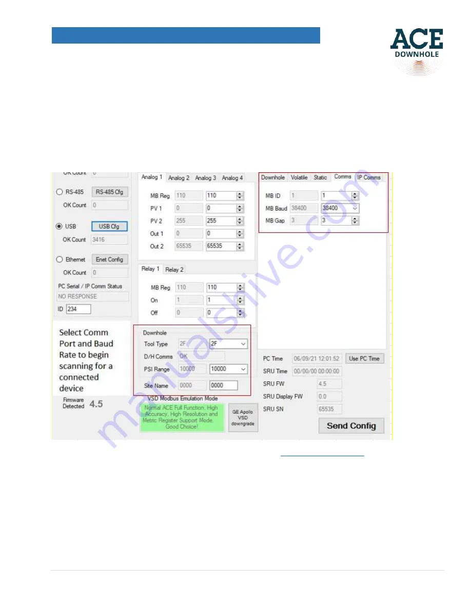
drop-down menu. If you have a single pressure, single temperature sensor with a standard sampling rate, you
need to select 2 in the drop-down menu. To configure your SRU Optix for SCADA communication go to Comms
menu in the top right hand side corner. In the Comms menu you are able to assign Modbus ID (MD ID), select a
Modbus Baud rate that fits your field communication system (most common- 38,400) and MB Gap ( delay which
you want your SRU Optix to respond to commands from SCADA.
Once configuration is complete, press the “Send
Config” button to push these settings into the SRU Optix.
Figure 41
The correct port # is
selected and the PC Serial /IP Comm Status is “OK”
8.5. Please see the appendix of the ACE ESP Operations Manual at
9.
Accessing downhole sensor data wirelessly from your device
9.1
On your cell phone or a tablet go to “Settings > WiFi” and connect to the ACE OPTIX WiFi network. The last
four letters in the WiFI network (2CDO shown below) are the last 4 letters of the ACE Optix device MAC address,
so will be different for all ACE Optix devices, allowing them to be identified if several are running close together.
Summary of Contents for Reliance 1K
Page 1: ...V2 4 1 P a g e ACE RELIANCE SENSOR OPERATIONS MANUAL ACE Reliance Sensor Operations Manual...
Page 8: ...V2 4 8 P a g e ACE RELIANCE SENSOR OPERATIONS MANUAL Figure 9 Vise grips Figure 10 Tube cutter...
Page 26: ...V2 4 26 P a g e ACE RELIANCE SENSOR OPERATIONS MANUAL Figure 43 SRU Optix set up menu...


