Rev. 201609V3
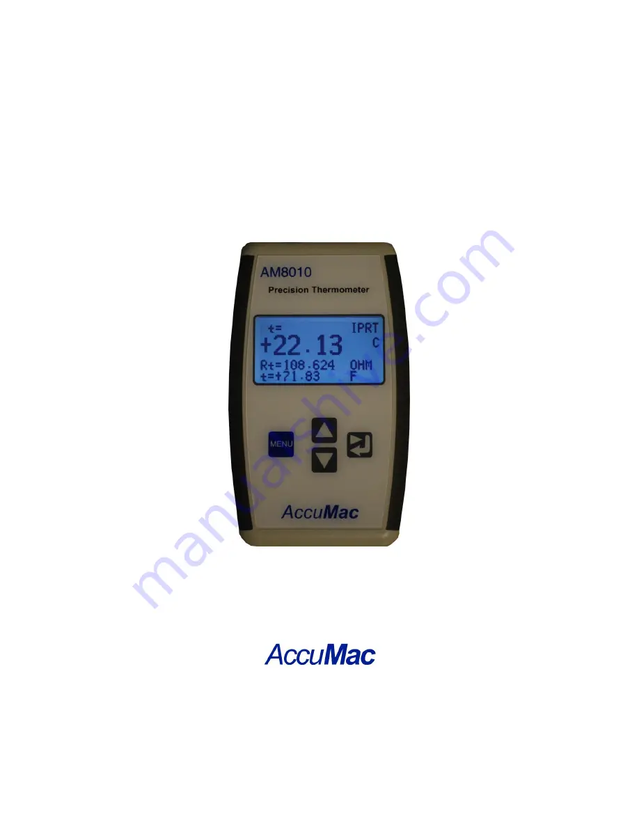
AM8010 Precision Thermometer
User’s Guide
Please download the latest version at www.accumac.com
Page 1: ...Rev 201609V3 AM8010 Precision Thermometer User s Guide Please download the latest version at www accumac com...
Page 2: ...4 4 Sensor Connection 7 4 5 Power On Off Control 8 4 6 Display of Measurement Results 8 4 7 Touchpad Operation 9 5 Connecting to a Computer Using USB Interface 10 5 1 Installation of USB Driver to a...
Page 3: ...ries and the field Users should read and understand the following Warning to avoid electrical shocks and injuries Warnings Do NOT use the instrument in applications other than specified as temperature...
Page 4: ...eatures of AM8010 Precision Thermometer include the followings High accuracy up to 0 03 C High resolution 0 01 C Flexible sensor selection o 100 ohm PRT with temperature coefficient 0 00385 o 100 ohm...
Page 5: ...full range Stability 0 01 C per year Probe 100 RTD PRT or SPRT Characterizations ITS 90 coefficients Callender Van Dusen coefficients IEC 751 DIN 385 Sample Interval 1 second Display 2 7 inch LCD Disp...
Page 6: ...switch OFF ON Figure 3 2 AM8010 Top Panel A foldable tilt foot support is mounted on the back of AM8010 It helps user to put the meter in a stable position with a display angle There is a battery cove...
Page 7: ...wings 1 Turn off AM8010 2 Open the battery cover at the back side of AM8010 Mode Switch which is a sliding switch is located besides the battery holder 3 Text MEA and ADJ indicate whether AM8010 is se...
Page 8: ...8010 is already powered by batteries and the power switch is on the backlight of LCD should illuminate 5 The USB cable can be unplugged anytime If AM8010 is powered by batteries functionality will con...
Page 9: ...dications The first line is the status information line The second third and fourth line shows the measured data which are temperature or sensor resistance As shown Figure 3 1 the top line is the stat...
Page 10: ...ults with larger fonts to help users to focus on the key readings The information of second third and fourth line can be scrolled up or down based on the user s preference 4 7 Touchpad Operation There...
Page 11: ...river to a Computer Important Update if your PC is running Windows 7 or later versions operating system you can skip USB driver installation process These versions of windows OS provide plug and play...
Page 12: ...AM8010 Precision Thermometer User s Guide Rev 201609V3 11 30 e Select No not this time then click on Next f Select Install from a list or specific location Advanced and then click on Next...
Page 13: ...se to find the driver in E refer to the above figure then click on Next h Select Continue Anyway the computer may request for another file FTD2XX sys i Use Browse to search E drive to find and select...
Page 14: ...010 Precision Thermometer User s Guide Rev 201609V3 13 30 j Click Finish to end the installation k The computer should show Your new hardware is ready to use to indicate that the installation is finis...
Page 15: ...to a file Details of setting up the data acquisition system using the software are as follows a Turn on the computer and copy the software Cool Edge USB Viewer from the CD provided to the desktop b Co...
Page 16: ...the sampling rate The above Figure shows the Data Saving and the default sampling rate is 1 sec if other sampling rates are required users can key in other integer numbers between 1 to 65535 seconds U...
Page 17: ...p the sensor s triple point of water a4 b4 ow temperature range parameters a b c high temperature range parameters for some type of sensors b and c may equal to 0 Refer to ITS 90 for details After use...
Page 18: ...nds the bottom right corner of LCD should show MENU Then hold the MENU key and also press the key at the same time AM8010 should enter into adjustment program 5 The following will be displayed on LCD...
Page 19: ...anged Moving the highlight line to the correct line by press or and then press key to select The program will move into parameter adjustment section as illustrated in step 8 8 For example if IPRT is s...
Page 20: ...and the LCD will show Menu Save Enter Shift R0 OHM 100 0100 ii The value of second line shows the current R0 value The cursor shows the adjust position To modify the value press or to adjust the valu...
Page 21: ...he LCD should show Menu Exit Enter Yes a4 4 129934e 05 SET a4 0 ADJUST a4 ii The first line is the current a4 value The second line should be selected if a4 0 The third line allows the user to adjust...
Page 22: ...key and the LCD should show Menu Exit Enter Yes SAVE a4 4 129934 e 05 iv The first line display SAVE to remind user that the meter is preparing to save the new a4 value the flashing second line is to...
Page 23: ...strument Calibration and System Calibration 7 1 Instrument Calibration Instrument Calibration is to calibrate the resistance measurement accuracy of AM8010 Note a standard resistor with resistance of...
Page 24: ...ernal standard resistor resistance reading Rt 99 9888 ohm which is not equal to the real external standard resistor value 100 0038 ohm The following Instrument Calibration procedures are to adjust the...
Page 25: ...urement Mode 7 2 System Calibration System Calibration is based on the Instrument Calibration It is to integrate a particular PRT sensor with AM8010 after Instrument Calibration to form a temperature...
Page 26: ...tion three temperature points are needed which are ice point triple points of water temperature close to upper limit and a point in between Note down the measurement results at all these three points...
Page 27: ...igh precision 100 ohm or standard 100 ohm Platinum Resistance Thermometer with temperature coefficient 0 003925 WGa 1 11807 1 Turn off power of AM8010 set it to Measurement Mode See Chapter 4 1 2 Conn...
Page 28: ...t values T90 t 273 15 R 0 01 is the sensor s triple points of water and R 0 01 is named as Rtp in AM8010 The details can be found in ITS 90 standard The sensor s parameters a b and c can be calculated...
Page 29: ...ere are 5 pins on the connector For a 4 wire platinum sensor pin1 and pin2 should be one end of the sensor and pin4 and pin5 should be the other end of the sensor Pin3 can be optionally connected to c...
Page 30: ...warranty terms in the separate agreement shall control Each product from AccuMac Corporation is warranted to be free from defects in material and workmanship under normal use and service The warranty...