background image


30 

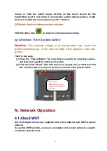
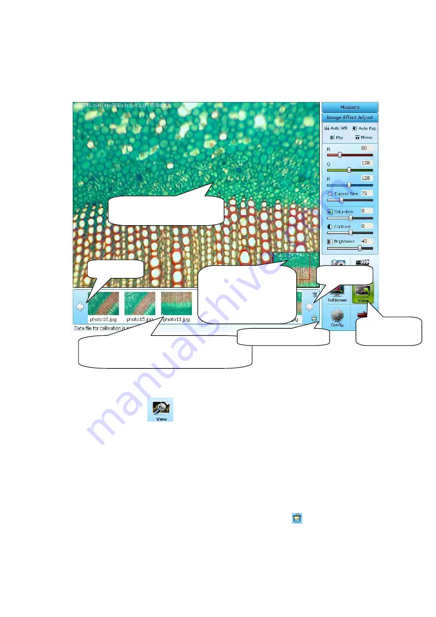
(f) Image Preview Window 


(1) Switch to the image preview window: 

Click  the  view  icon 

  to  switch  from  video  preview  to  image  preview.   

The image preview window displays partial enlargement image, you can drag 
the  red  rectangle  in  the  panoramic  image  to  adjust  the  part  of  image  to 
enlarge preview. 
Double  click  a  select  image  in  the  image  index  bar  to  access  to  the  image 
preview window. 

(2) Delete an image: 

Select the image you want to delete, or click the icon

, the system will ask 

you to check delete, click ok if you want to delete, and click cancel if you don‟t 
want to delete.   

Equivalent  Command: 

Use  the  right  click  function,  use  the  right  key  of the 

Image Index Bar: Displays the captured images 

Double click the select image to preview. 

Panoramic image, move 

the red rectangle to adjust 

the partial of image to 

enlarge preview.   

Enlarge preview the partial of 

image in the red rectangle. 

Switching 

to 

video preview 

Last Page 

Next Page 

Delete the select image. 

Summary of Contents for 3025-LCD

Page 1: ...MANUAL 73 Mall Drive Commack NY 11725 631 864 1000 P 631 543 8900 F www accu scope com info accu scope com 3025 LCD MICROSCOPE SYSTEM ...

Page 2: ...st 12 d Buttons function 15 e Dimension Calibration and Dynamic Measurement 18 Dimension Calibration 20 Length Measurement 24 Rectangle Measurement 25 Color Selecting 25 Reticle Ruler 26 Store the measurement result 28 f Image Preview 30 g Attention If the System halted 31 IV Network Operation 31 4 1 About WIFI 31 4 2 Communication Model 32 a Network Communication With the LAN 32 b Point to Point ...

Page 3: ...CD microscope begins to send images 51 4 The PC begin to receive images 52 4 4 2 By Network Cable crossover cable 54 1 Set the LCD microscope 54 2 Set the PC 54 3 The LCD microscope begin to send images 56 4 The PC begins to receive images 57 V Common Failure and Solution 59 5 1 Electric section 60 a Error messages 60 b Cannot switch on the system 61 c Blurred image on LCD 61 d Right key function ...

Page 4: ...n high resolution 2 Megapixel camera provides high quality images 5 Powerful software with international advanced technology Support real time preview dynamic calibrating and measuring and can capture images or videos 6 LCD screen rotatable at maximum 30 elevation angle and 180 pivoting makes the observation much more comfortable and is suitable for long time observation 7 Touch screen easy to ope...

Page 5: ... 4 times White balance adjustment and image correction Electronic viewfinder and screen menu function Human machine interface 8 4 Inch Diagonal TFT liquid crystal display resolution 800x600 Support keyboard mouse input Hardware switch button reset soft switch button power switch Can configure touching and handwriting function according to customer s demands Extend card Support up to 4G High Speed ...

Page 6: ...y LED indicator light Simple Chinese or English WINCE 5 0 operating system Support Media Player software and can choose applications as Word Excel and so on according to the customers needs 1 4 Camera Specification LCD Size 8 4 Inch TFT Touch Screen Image Sensor 1 3 2 CMOS Valid Pixel 1600 1200 2 0M Pixel Pixel Size 2 8um 2 8um Digital Output 24 bit color Image Format frame rate 1600 1200 7 5f s 8...

Page 7: ...ive Infinitive Semi plan Achromatic Objectives 4 10 40 100 Nosepiece Quadruple Nosepiece Stage Double Layers Mechanical Stage 140mm 140mm 75mm 50mm Condenser Sliding in centerable condenser NA12 5 Focusing Coaxial Coarse Fine Adjustment Moving Range 20mm Lumination 6V 20W Halogen Lamp Brightness Adjustable Phase Contrast Kit Dark Field Attachment Note Standard Outfit Optional 2 Objectives plan ach...

Page 8: ...ce 100M Ethernet network AV Output VGA Output Monitor input DC 12V Handwriting Pen Data interface Reset the system SD Card interface Audio output USB Port can link with USB disk keyboard mouse and so on Mini USB Port Capture button Power Switch Microphone Position for Manufacturer preset Please don t adjust by yourself ...

Page 9: ...e microscope with the plastic cover while not in use Ⅲ Usage and Operating 3 1 Windows CE a About Windows CE Windows CE also known officially as Windows Embedded CE and sometimes abbreviated WinCE is a variation of Microsoft s Windows operating system for minimalistic computers and embedded systems Like the full scale Windows systems Windows CE is a 32 bit multitasking multithreading operating sys...

Page 10: ...ng many elements of the familiar Desk Top Windows user interface is also available facilitating ease of use for end users The meaning of C and E in Windows CE C Stands for E stands for Compact Electronics Consumer Connectivity Companion b Open the Soft keyboard Besides the keyboard you can link a keyboard with the USB port thanks to the touch screen the system also supports the soft keyboard Click...

Page 11: ...ck for more than 2 seconds for the system to respond as a right click For Example Select the file and click it for more than 2 seconds the right click menu will come out as follows d Get the help Click the icon on the command bar WinCE help window comes out Just click the items you want The system will give out the relevant help information Click Hide Input Panel ...

Page 12: ...tal images The main function is as follows 1 Real time preview images 2 Adjust the color 3 Capture images 4 Record videos 5 View the captured image 6 Real time measurement 7 Support WIFI function can communicate with the PC by wired network or wireless network can receive and display the real time images on the PC b Start NMS 1 Turn on the power to start the WinCE5 0 operating system ...

Page 13: ...40x480 b Tools Located on the right of the main window there are various tools buttons and icons c Image Index Located under the video or image preview window and display the captured images d Status Bar Located at the bottom of the main window Depending on a still image or displaying video in the active image window the status bar gives different information c Image Effect Adjust ...

Page 14: ...ntion the default station is set to auto exposure And you can only adjust the exposure value when it has been set to manual exposure Vertical Flip Flip the active image by the horizontal axis press to set or reset a flip state When the active image window is showing the live images the command actually flips the live images Horizontal Flip Flip the active image by the Vertical axis press to set or...

Page 15: ...les Vertical Flip Original Image After click the Flip button Horizontal Flip Original Image After click the Mirror button Vertical and Horizontal Flip Original Image After click both the Flip and mirror button ...

Page 16: ...t the Brightness of the screen Attention 1 If you press the button you can not adjust the RGB values for it is at the auto white balance station 2 For the same reason you can only adjust the Exposure value when it is at manual exposure station not press the button down 3 Move the slider of the RGB value can adjust the color of the image and the adjust result can be stored into the image 4 Move the...

Page 17: ...creen display the active image Equivalent Command Double click the active image on the video preview window to access full screen preview and double click again to return back Click this button to switch between active video window and captured image preview window This commend configure the capture option resolution format store path the video sender information IP address and port and so on The ...

Page 18: ...d images are stored in images folder in the SD Card Click to turn off the sound Click Clear button to reset the photo number to 0 click OK to check or click X to cancel 2 The image store folder 1 Set the Capture Parameter 3 The Video store folder 6 The version information 5 Reset the camera when the camera works wrong 4 Set the IP address of the target PC And send the images to the PC receiving en...

Page 19: ...imension Calibration and Dynamic Measurement NMS supplies several measurement tools it supports dimension calibration and dynamic measurement To do the measurement simply click on the image to define control points The program will automatically perform measurements and calculate areas All measurements are drawn over a special measurement layer It is simple convenient easy to learn and suitable fo...

Page 20: ...k Measure the system will switch from the Image Effect Adjust to the Measure Click Image Effect Adjust the system will switch from the Measure to the Image Effect Adjust Click Measure Click Image Effect Adjust ...

Page 21: ...the measure tools Dimension Calibration Here the objective is 10X and the micrometer is 0 1mm 1 Put a micrometer on the stage select the objective example here is 10X focus the microscope to make the micrometer display clearly on the LCD screen 2 Switch the command bar from Image Effect Adjust to Measure Click Measure ...

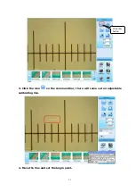
Page 22: ...21 3 Click the icon on the command bar there will come out an adjustable calibrating line 4 Move the line and set the begin point Click this button ...

Page 23: ...22 5 Set the end point 6 Set the objective magnification length unit and input the actual length with the keyboard or the soft keyboard ...

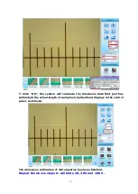
Page 24: ...he dimension data that just has calibrated the actual length of each pixel by itself and displays in the control panel as follows The dimension calibration of 10X objective has been finished Repeat the above steps to calibrate 4X 40X and 100 X ...

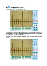
Page 25: ...ine to the place you want to measure Set the begin point and the end point of the line the system will then calculate the length itself according to the dimension you have just calibrated Here the result of line length is 203 08um and is coincident with the actual length ...

Page 26: ...tool appears click the center or the four corners of the rectangle with the mouse or writing pen you can drag the seletction to magnify or reduce the rectangle Color Selecting 1 Click this button a color plate appears select your color preference to set the line color ...

Page 27: ...auve Reticle Ruler 1 Click the reticle button There will be a reticle tool on the image click the center of the reticle with the mouse or writing pen a red square in the center of the reticle will appear when you drag the square the reticle will move ...

Page 28: ... At the same time the control panel will display the minimum scale value of the current reticle after dimension calibrating 2 Click the center of the reticle and a square appears you can move the square to any place you want ...

Page 29: ...28 Store the measurement result In order to store the measurement result you should set the resolution to 640x480 Reserve ruler first as the picture below ...

Page 30: ...29 Capture an image with the measurement result Preview the captured image photo27 bmp ...

Page 31: ... window 2 Delete an image Select the image you want to delete or click the icon the system will ask you to check delete click ok if you want to delete and click cancel if you don t want to delete Equivalent Command Use the right click function use the right key of the Image Index Bar Displays the captured images Double click the select image to preview Panoramic image move the red rectangle to adj...

Page 32: ...not work normally If this happens reset your system There re two ways 1 Press the Power Button for more than 2 seconds to close the system and then press again to restart your system 2 Click the small Reset hole with the end of a paper clip or other tool that has a small point to reset your system as shown in the picture below IV Network Operation 4 1 About WIFI Our LCD digital microscope supports...

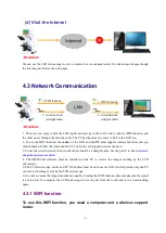
Page 33: ...less function and you should check whether the router and the PC s network card support wireless function 3 To use the wired network the network cable should be a straight cable See the part V to know what are straight and crossover cable 4 The PC receiver must install the NMSClient software to receive the images sending by the LCD microscope 5 The LCD microscope router and PC s IP address must on...

Page 34: ... LCD Microscope and PC the network cable must be a crossover cable See the part V to know what are straight and crossover cable 3 The NMSClient software must be installed on the PC to receive the images sent by the LCD microscope 4 In this model one LCD microscope can only communicate with one PC it can not communicate with more than two PCs 5 In order to ensure the image transmission quality when...

Page 35: ... To use the wired network the network cable should be a straight cable See the part V to know what are straight and crossover cable 4 The NMSClient software must be installed on the PC to receive the images sending by the LCD microscope 5 The LCD microscope router and PC s IP address must be on the same LAN And at present only one PC can receive the images sent by the LCD microscope 6 In order to ...

Page 36: ...he button Connect As the picture shows below The LCD will connect to the router and get the IP address by itself 2 Link the PC to the LAN The PC can link to the router by WIFI function or by network cable Here we show a wireless network For a wired network please see the chapter 4 3 2 Wired Network 1 The system will search the networks by itself and list all of them out Please select a wireless ro...

Page 37: ... please make sure your PC has a wireless network card and supports wireless function 1 Double click the icon on the task bar 2 Click the Connect button The PC will connect the router and get the IP address by itself Click Connect button ...

Page 38: ...37 3 Now the wireless icon on the task bar displays as double click it 4 Check the IP address and record it 3 The LCD microscope begins to send images 1 Start your software NMS Click Support ...

Page 39: ...reless net The button now changes from Start to Stop you can click Stop to stop sending Now we have finished the setting of the LCD digital and it is sending video you can click Stop to stop sending video 4 The PC begin to receive images 1 Make sure the software NMSClient has been installed on the PC 2 Launch the NMSClient software 3 Click the Receive button Input the PC s IP address Then click St...

Page 40: ... should be the same And make sure your microscope video sender has been started 4 The NMSClient begins to receive video and displays the real time video You can capture images or record videos The port number should the same as the NMSClient Click Receive to begin ...

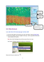
Page 41: ...he LCD digital microscope and the operation is the same as the Windows XP system Note the LCD s IP address should in the same LAN as the router Click Start Settings Network and Dial up Connections Double click the wire network icon Set the video saving path Set the image saving path Click this button to capture the video click again to stop capturing Capture a frame ...

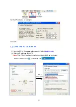
Page 42: ...k OK 2 Link the PC to the LAN 1 Link the PC to the router with network cable straight cable 2 Set the IP address of the PC Note The PC s IP address should in the same LAN as the router Double click the icon on the task bar Click Properties ...

Page 43: ...e IP address of the PC if the PC begins to receive you will find the local area connection status displays as follows 3 The LCD microscope begins to send images Click Internet Protocol TCP IP Connected Begin to receive data ...

Page 44: ...range from 2000 to 5000 and click Start button the system begins to send the datas The button now changes from Start to Stop you can click Stop to stop send 4 The PC begin to receive images 1 Make sure the software NMSClient has been installed in the PC 2 Launch the NMSClient software 3 Click the Receive button Click Start Input the PC s IP address ...

Page 45: ...s the real time video You can capture images or record videos Set the video saving path Set the image saving path Click this button to capture the video click again to stop capturing Capture a frame The port number should the same as the NMSClient Click Receive to begin ...

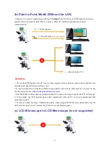
Page 46: ... it cannot communicate with more than two PCs 5 In order to ensure the image transmission quality when using the WIFI function please make sure the LCD microscope is not very far from the PC and in a non blocking space 4 4 1 WIFI Function For point to point communication you need a computer with a wireless network card The LCD Digital Microscope communicates with the PC directly without a router 1...

Page 47: ...uter to computer network has been setup Double click Add New Step1 Input a network name Step2 Select this box Step3 Set to Disabled Step4 Click OK 1 Select the net you have just set connection is the one that has a blue circle on the icon 2 Click Connect ...

Page 48: ...ttings Network and Dial up Connections Double click the wireless icon Set the IP address for example Click OK 2 Link the PC to the new network Make sure your PC has a wireless network card and the card has the installed driver First you should set the PC s IP address to the same LAN as the LCD digital microscope ...

Page 49: ...k Places icon on the desktop click Properties 2 Double click the Wireless Network Connection There will come out a Wireless Network Connection Status dialog Or you can also get this dialog by double clicking the icon on the task bar ...

Page 50: ...system will search the wireless network by itself please select the Point to Point network you have just created If not please click the Refresh network list on the left control bar Then click the button Connect ...

Page 51: ...50 4 Click Properties Click Properties ...

Page 52: ...suring software NMS 6 Click the button a Configure dialog box appears Set the IP Address reference the router port number rang from 2000 to 5000 and click the Start button the system begins to send the data via WIFI wireless network The button now changes from Start to Stop you can click Stop to stop sending Click Internet Protocol TCP IP Properties ...

Page 53: ...e the software NMSClient has been installed in the PC 2 Launch the NMSClient software 3 Click the Receive button Attention The port number of video sender and the NMSClient should be the same Make sure your microscope video sender has been started ...

Page 54: ...the Unblock button 4 The NMSClient begins to receive video and displays the real time video You can capture images or record videos Set the video saving path Set the image saving path Click this button to capture the video click again to stop capturing Capture a frame Click Start ...

Page 55: ...l microscope to the PC with network cable crossover cable 2 Set the IP address of the LCD digital microscope Click Start Settings Network and Dial up Connections Double click the wired network icon Set the IP address for example Click OK 2 Set the PC 1 Double click the icon on the task bar ...

Page 56: ...55 Now we have set the IP address of the PC if the PC begins to receive you will find the local area connection status display as follows Click Properties Click Internet Protocol TCP IP ...

Page 57: ...dialog set the IP Address The IP Address of the PC port number range from 2000 to 5000 and click the Start button the system begins to send the data via WIFI wireless network The button now changes from Start to Stop you can click Stop to stop sending Connected The packets number will be changed if it begins to receive data ...

Page 58: ... sending video you can click Stop to stop sending video 4 The PC begin to receive images 1 Make sure the software NMSClient has been installed in the PC 2 Launch the NMSClient software 3 Click the Receive button Click Start Input the PC s IP address Then click Start ...

Page 59: ...on The port number of video sender and the NMSClient should be the same Make sure your microscope video sender has been started Click Start The port number should the same as the NMSClient Click Receive to begin ...

Page 60: ...and displays the real time video You can capture images or record videos V Common Failure and Solution When failure occurs please look up the cause from the codes listed below to get rid of the failure Set the video saving path Set the image saving path Click this button to capture the video click again to stop capturing Capture a frame ...

Page 61: ...D card Code 5 Solution The SD card is not in the position check and put it in the position Code6 Indication SD card maybe full please check Code 6 Solution Check whether the SD card is full make sure the SD Card has enough memory space Code7 Indication Capture failed Code 7 please reset camera by clicking Reset button on Config Dialog window Solution Click the button to open the configure dialog a...

Page 62: ...ta transfer isn t connected tightly Solutions Check and link again Make sure the connection is secure tight Very important d Right key function Problem Cannot use the right key function of the digital LCD Solutions 1 Use a mouse to operate just plug a mouse to the USB port of the LCD 2 Use the handwriting pen press for more than 2 seconds the system will respond as a right click e System Stopped o...

Page 63: ...tions Recalibrate your screen again Do as follows 1 Enter the control panel 2 Double click the Stylus button a Stylus Properties dialog box appears click the Recalibrate button Manufacturer Operation hole Please don t use Data transfer interface Make sure the line connect tightly with the interface otherwise it may cause the blur image or unstable system ...

Page 64: ...shair in the center of the screen Carefully press and briefly hold stylus on the center of the target Press the Esc key to cancel As follows 4 Repeat as the target moves around the screen Press the Esc key to cancel As follows ...

Page 65: ...alibration settings have been measured Press the Enter key to accept the new settings Press the Esc key to keep the old settings 6 Now the screen recalibration has been finished you can use the touch screen again ...

Page 66: ...er cable can be Cat 5 Cat 5e or Cat 6 UTP cable the only difference is each type will have different wire arrangement in the cable for serving different purposes Straight Cable You usually use straight cable to connect different types of devices This type of cable can be used to 1 Connect a computer to a switch hub s normal port 2 Connect a computer to a cable DSL modem s LAN port 3 Connect a rout...

Page 67: ...o 1 Connect 2 computers directly 2 Connect a router s LAN port to a switch hub s normal port normally used for expanding network 3 Connect 2 switches hubs by using normal port in both switches hubs In you need to check what crossover cable looks like both side side A and side B of cable have wire arrangement with following different color ...

Page 68: ...es and see which works Note If there is auto MDI MDI X feature support on the switch hub network card or other network devices you don t have to use crossover cable in the situation which I mentioned above This is because crossover function would be enabled automatically when it s needed ...

Page 69: ...warranted for a period of one year from the date of invoice to the original end user purchaser The camera LCD screen are warranted for a period of one year from the date of invoice to the original end user purchaser This warranty does not cover damage caused in transit misuse neglect abuse or damage resulting from improper servicing or modification by other then ACCU SCOPE approved service personn...

Reviews: