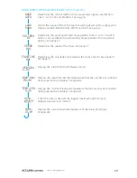
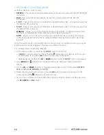
background image

3

www.acclaimlighting.com

INSTALLATION

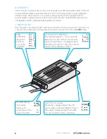
The majority of this guide covers the multi-port 

AL Driver 200

AL Driver 400

 and 

AL 

Driver 800

 models. For details about the single port 

AL Driver 1

 and 

AL Driver 4

 models, 

please see pages 8 and10 respectively.

MOUNTING

The AL Driver 200, 400 and 800 models can be wall mounted either vertically (with the output 
connectors facing downwards) or horizontally as required. Four slotted holes (Ø 0.55”/14mm 
leading to Ø 0.31”/8mm) are built into the backplane for mounting purposes.  

INPUT CONNECTIONS

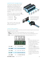
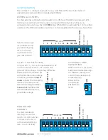
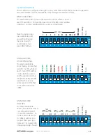
AL Drivers can be controlled by any of four external signal types: DMX, DALI, 1-10V or 0-10V. 
DMX and DALI are digital signals that allow multiple channels to be addressed; 0-10V and 
1-10V are analog signals that can control one channel only (all outputs will respond equally 
when 0-10V/1-10V modes are used). 

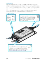
DMX

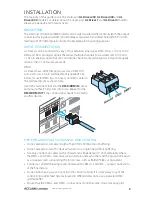
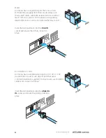
AL Drivers have a DMX IN port as well as a DMX OUT 
port. Each uses a 3-pin terminal block (supplied). See 
below for useful DMX tips. Connect your DMX cables to 
the terminal blocks as shown here:
Insert the terminal block into the 

DMX/RDM IN

 socket 

and ensure that it fully clicks into place. Repeat for the 

DMX/RDM OUT

 if the control signal needs to be fed to 

another device.  

TIPS FOR ACHIEVING SUCCESSFUL DMX CONTROL


Do not exceed a total cable length of 3,900 ft (1200m) without buffering.


Do not exceed a total of 32 devices/fixtures on a single line without buffering.  


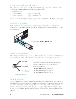
Use only connection cables with a characteristic impedance of 120Ω, preferably where 
the DMX + and DMX – data lines are twisted around each other and the ground link exists 
as a coaxial screen surrounding the inner cores, such as Belden® 9842 or equivalent. 


Connect a 120Ω terminating resistor between the DMX + and DMX – output connections 
of the final fixture. 


Do not introduce a passive Y-split into the control cabling. If it is necessary to split the 
control link in order feed fixtures located in different directions, use a powered DMX 
splitter/buffer. 


Ensure that the DMX + and DMX – connections do not become crossed at any point.  

Fu

se

25

0V

/8A

V

+

V

+

R

e

d

-

G

re

e

n

-

B

lu

e

-

W

h

it

e

-

1

Fu

se

25

0V

/8A

V

+

V

+

R

e

d

-

G

re

e

n

-

B

lu

e

-

W

h

it

e

-

3

1=

Gr

ou

nd

2 =

D A

TA

-

3 =

D A

TA

+

DM

X/

RD

M

OU

T

3

2

1

AN

AL

OG

IN

0-10V/1-10V

GN

D

DA

LI

IN

DA

DA

D M

X /

R D

M

I N

3

2

1

Summary of Contents for AL Driver series

Page 1: ...A DA DMX RDM IN 3 2 1 O N 2 3 4 5 6 7 8 9 1 0 1 1 1 2 1 G N D G N D G N D G N D 1 2 2 4 V 1 2 2 4 V D M X I N D M X O U T D C I N D a t a D a t a D a t a D a t a 8 A D M X A d d r e s s S e t t i n g...

Page 2: ......

Page 3: ...iver 800 Channel and load settings DMX and DALI 21 Choosing a base address DMX and DALI 22 Choosing the load type Manual and Auto modes 22 Setting a static color mix Manual mode 23 Choosing a chase pa...

Page 4: ...Driver 4 accepts DMX only Additionally you can use all AL Drivers independently of any external control Depending on the model they can create static color mixes set dimming levels for single color or...

Page 5: ...nal blocks as shown here Insert the terminal block into the DMX RDM IN socket and ensure that it fully clicks into place Repeat for the DMX RDM OUT if the control signal needs to be fed to another dev...

Page 6: ...0 10V AND 1 10V AL Drivers have a single analog input port 0 10V or 1 10V current sink or source see page 2 port that uses a 2 pin terminal block supplied For best results use shielded cables and conn...

Page 7: ...operate is determined primarily by three important menu settings MODE determines the control method DMX DALI 0 10V etc page 18 CHANNEL determines how the ports are assigned to the control method pages...

Page 8: ...currents without tripping during startup AL Driver 200 400 and 800 models operate from supplies in the range 100 277VAC 50 60Hz Power consumption AL Driver 200 220W maximum AL Driver 400 480W maximum...

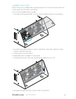
Page 9: ...RDM OUT 3 2 1 ANALOG IN 0 10V 1 10V GND DALI IN DA DA DMX RDM IN 3 2 1 CONNECTOR COVER Each AL Driver unit is supplied with a transparent plastic cover to provide protection to the control inputs and...

Page 10: ...U R V E 1 1 0 V D i m D M X A S D D R E S S E T T I N G G N D G N D G N D G N D G N D 0 1 0 V 1 1 0 V 0 1 0 V 1 1 0 V D C 6 1 2 V 5 A D C 2 4 V 4 A D M X I N I N T H R U O U T P U T D M X O U T I N P...

Page 11: ...the DMX start address Switches 1 to 9 are weighted with a value as shown here 256 128 64 32 16 DMX mode Manual 0 10V 1 10V Curve 8 DMX address 4 2 1 9 11 6 3 8 5 2 10 12 7 4 1 ON 128 64 32 16 DMX Manu...

Page 12: ...T D C I N D a t a D a t a D a t a D a t a 8 A D M X A d d r e s s S e t t i n g 1 2 3 D M X m o d e D i m m i n g m o d e B u i l t i n m o d e 4 5 6 7 8 9 1 0 1 1 1 2 O U T P U T W h i t e B l u e G...

Page 13: ...hown at 100 STANDALONE CHASES To select standalone chases ensure that switch 12 is ON while 10 and 11 are OFF Switches 1 to 3 select the Fade time 0 to 100 switches 4 to 6 adjust the Speed 0 to 30s an...

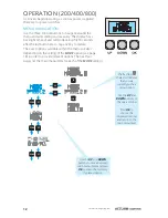
Page 14: ...roughly 30 seconds after the last button press tap any key to restore The exact options available within the menu will alter depending on the setting of the MODE option see page 18 in order to provid...

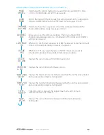
Page 15: ...NEL settings See page 22 When set to ON the last received set of DMX values will be latched and will remain on the outputs during instances of signal loss When set to YES any rapid changes in the DMX...

Page 16: ...of DALI channels required depends on a combination of the LOAD and CHANNEL settings See page 22 Displays the current internal firmware version Displays the maximum internal temperature that the unit...

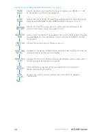
Page 17: ...n in degrees Centigrade Displays the minimum internal temperature that the unit has encountered during operation in degrees Centigrade Displays the current internal temperature of the driver in degree...

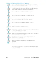
Page 18: ...channel See page 23 Displays the current internal firmware version Displays the maximum internal temperature that the unit has encountered during operation in degrees Centigrade Displays the minimum...

Page 19: ...the chase See page 23 Determines the crossfade time between the steps of each chase pattern See page 23 Displays the current internal firmware version Displays the maximum internal temperature that th...

Page 20: ...any external control input See page 23 Note The control mode and the DMX address can optionally be configured remotely using the RDM Remote Device Management protocol via a DMX connection TO CHOOSE A...

Page 21: ...OAD types RGBW RGB Ai Dim WHITE and DW Press the OK button to select the one that matches your connected fixture type 4 Use the DOWN button to show the CHANNEL option and press the OK button to enter...

Page 22: ...DOWN button to show the CHANNEL option and press the OK button to enter 5 Use the UP and DOWN buttons to change between the various CHANNEL groupings xxx M0 xxx M1 xxx M2 and xxx M3 Where xxx is the s...

Page 23: ...e DOWN button to show the CHANNEL option and press the OK button to enter 5 Use the UP and DOWN buttons to change between the various CHANNEL groupings xxx M0 xxx M1 xxx M2 and xxx M3 Where xxx is the...

Page 24: ...SS option and press the OK button to enter 3 Use the UP and DOWN buttons to display the required base address and press the OK button to select it Pages 26 to 34 show you exactly how the channels of e...

Page 25: ...MODE Auto mode allows you to choose from ten different pre programmed color chase patterns independently of any external control input The available chase programs are labeled 00 to 10 and there is al...

Page 26: ...evices and after a short while the XMT 350 will display a list of all located devices 3 On the XMT 350 press the right arrow button to change to the PATCH tab 4 If necessary use the up down buttons to...

Page 27: ...ixtures The driver highlighted in the list should show output from its emitters to identify itself 3 If necessary use the up down buttons to highlight an alternative fixture 4 Press the button to view...

Page 28: ...ions see page 22 The remaining ports will be placed at successive DMX DALI addresses CHANNEL CHANNEL CHANNEL Address 016 M02 008 M01 004 M00 1 Port 1 Red Ports 1 2 Red All ports Red 2 Port 1 Green Por...

Page 29: ...the base address determined by the DMX or DALI menu options see page 22 The remaining ports will be placed at successive DMX DALI addresses CHANNEL CHANNEL CHANNEL Address 012 M02 006 M01 003 M00 1 Po...

Page 30: ...e W1 W2 W3 and W4 emitters on the Ai Dim product such as Ai Flex respectively In WHITE mode for each port the White outputs are placed on all of the contacts Red Green Blue and White Together with the...

Page 31: ...ts 1 2 Red Ports 1 to 3 Red All ports Red 2 Port 1 Green Ports 1 2 Green Ports 1 to 3 Green All ports Green 3 Port 1 Blue Ports 1 2 Blue Ports 1 to 3 Blue All ports Blue 4 Port 1 White Ports 1 2 White...

Page 32: ...addresses CHANNEL CHANNEL CHANNEL CHANNEL Address 018 M03 009 M02 006 M01 003 M00 1 Port 1 Red Ports 1 2 Red Ports 1 to 3 Red All ports Red 2 Port 1 Green Ports 1 2 Green Ports 1 to 3 Green All ports...

Page 33: ...ex respectively In WHITE mode for each port the White outputs are placed on all of the contacts Red Green Blue and White Together with the dual V connections this allows you to distribute multiple fix...

Page 34: ...ue Ports 1 to 5 Blue All ports Blue 4 Port 1 White Ports 1 2 White Ports 1 to 5 White All ports White 5 Port 2 Red Ports 3 4 Red Ports 6 to 10 Red 6 Port 2 Green Ports 3 4 Green Ports 6 to 10 Green 7...

Page 35: ...2 Port 1 Green Ports 1 2 Green Ports 1 to 5 Green All ports Green 3 Port 1 Blue Ports 1 2 Blue Ports 1 to 5 Blue All ports Blue 4 Port 2 Red Ports 3 4 Red Ports 6 to 10 Red 5 Port 2 Green Ports 3 4 G...

Page 36: ...ts are placed on all of the contacts Red Green Blue and White Together with the dual V connections this allows you to distribute multiple fixtures between the contacts if required In DW mode the Red a...

Page 37: ...elease 1 0b AL DRIVER 200 400 AND 800 SPECIFICATIONS Control input protocols DMX RDM DALI 1 10V sink or 0 10V source Control output protocol Pulse width modulation PWM Input voltage 100 to 277VAC 50 6...

Page 38: ...Data Data DC 6 24V 5A Data Data GND GND GND GND GND 0 10V 1 10V 0 10V 1 10V DC 6 12V 5A DC 24V 4A IN THRU OUTPUT ON 2 3 4 5 6 7 8 9 11 10 12 1 3 19 81mm 3 54 90mm 1 57 40mm 0 78 20mm DMX Address Setti...

Page 39: ...37 www acclaimlighting com AL DRIVER 200 DIMENSIONS AL DRIVER 200 24V DALI DOWN UP OK DMX RDM 0 10V POWER 2 76 70mm 3 58 91mm 8 07 205mm 9 84 250mm 0 55 14mm 0 31 8mm 6 3 160mm Weight 3 96 lbs 1 8kg...

Page 40: ...38 www acclaimlighting com AL DRIVER 400 DIMENSIONS 3 15 80mm 5 91 150mm 11 5 292mm 13 4 340mm 0 55 14mm 0 31 8mm 9 06 230mm DALI AL DRIVER 400 24V DOWN UP OK DMX RDM 0 10V POWER Weight 8 4 lbs 3 8kg...

Page 41: ...39 www acclaimlighting com AL DRIVER 800 DIMENSIONS DALI AL DRIVER 800 24V DOWN UP OK DMX RDM 0 10V POWER 4 100mm 8 7 220mm 13 9 352mm 15 8 400mm 0 55 14mm 0 31 8mm 10 7 270mm Weight 14 4 lbs 6 5kg...

Page 42: ...rd party items not manufactures by Acclaim lighting During the period specified above Acclaim Lighting will replace defective parts at its expense and will absorb all expenses for warranty service and...

Page 43: ...41 www acclaimlighting com...

Page 44: ...www acclaimlighting com...

Reviews: