2 -Wire Intercom System
DE-596
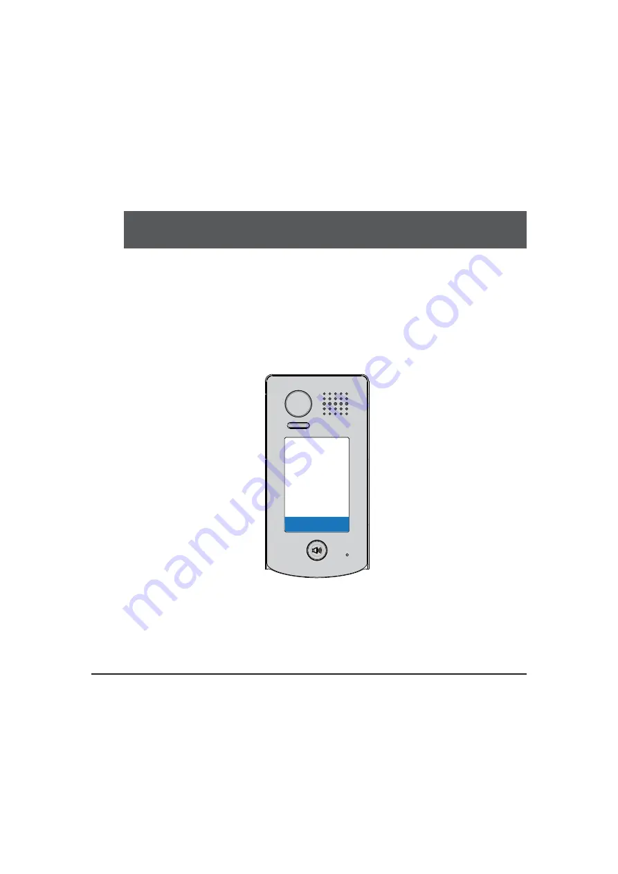
/KP User Manual
DT601/KP
14 5 6
9
80 #
7
2 3
*
ACCESS SECURITY PRODUCTS LTD
Page 1: ...2 Wire Intercom System DE 596 KP User Manual DT601 KP 1 4 5 6 9 8 0 7 2 3 A C C E S S S E C U R I T Y P R O D U C T S L T D...
Page 2: ...ounting 1 3 Terminal Descriptions 2 4 System Wiring and Connections 3 5 Functions Setting Up 9 6 Power Supply Instructions 17 7 Precaustions 17 6SHFL FDWLRQV 17 9 Cables Requirements 18 A C C E S S S...
Page 3: ...ophone 93 mm 28 mm 182 mm 1 4 5 6 9 8 0 7 2 3 Night Light 2 Mounting Drill holes in the wall to match the size of screws and attach the rainy cover to the wall Attach the panel to the rainy cover Use...
Page 4: ...pe Main Connect Port To connect the bus line and the electronic locks BUS Connect to the bus line no polarity PL External lock power input connect to the power positive power S Lock power output S Loc...
Page 5: ...c lock of Power on to unlock type should be used 2 The door lock is limited to 12V and holding current must be less than 250mA 3 The door lock control is not timed from Exit Button EB 4 The Unlock Mod...
Page 6: ...Installer setup Caliber TouchScreen Code Number 0010 Remove all remote control 0011 Add remote control 8000 Set as master unit 0 8001 Set as slaver unit 1 8002 Set as slaver unit 2 8003 Set as slaver...
Page 7: ...C DPS PS5 monitors 1 Camera 2 Camera 3 Camera 4 Camera DBC4 A B C D BUS L1 L2 PL S S L1 L2 PL S S L1 L2 PL S S L1 L2 PL S S Device Address 3 Device Address 2 Device Address 1 Device Address 0 A C C E...
Page 8: ...ors Connection monitor monitor monitor 85 260AC DPS PS5 Code 0 DIP 6 off Code 14 DIP 6 off Code 15 DIP 6 on 1 2 3 4 5 6 ON 1 2 3 4 5 6 ON 1 2 3 4 5 6 ON 1 4 5 6 9 8 0 7 2 3 Device Address 0 A C C E S...
Page 9: ...DPS PS5 1 2 3 4 5 6 ON 1 2 3 4 5 6 ON 1 2 3 4 5 6 ON 1 2 3 4 5 6 ON Code 15 DIP 6 on Code 13 DIP 6 on Code 3 DIP 6 on Code 1 DIP 6 on 1 2 3 4 5 6 ON 1 2 3 4 5 6 ON 1 2 3 4 5 6 ON 1 2 3 4 5 6 ON Code 1...
Page 10: ...DBC 4 A B C D IN OUT Code 0 DIP 6 on CALL UNLOCK TALK MON IN USE Code 3 DIP 6 on Code 2 DIP 6 on Code 1 DIP 6 on CALL UNLOCK TALK MON IN USE CALL UNLOCK TALK MON IN USE CALL UNLOCK TALK MON IN USE 1...
Page 11: ...g setting codes to continue the setting operation Press to exit the setting mode The example is set DV FDQFHO EXWWRQ DQG DV FRQ UP EXWWRQ SOHDVH UHIHU WR IXQFWLRQ setting for detail information Forbid...
Page 12: ...erference resistant grade settings Valid keys 0 5 2 09 11 MIC Adjustment Valid keys 0 9 7 10 12 SPK Adjustment Valid keys 0 9 7 11 13 Display Scene Valid keys 0 2 0 12 14 Night Light Level Valid keys...
Page 13: ...t 1s Inputting of new master code ex 4321 1 12 digits Input the setting code Inputting of code Input the setting code 1 Reset all settings 00 1234 4321 01 10 09 Input the setting code 02 Input the set...
Page 14: ...ster code Restore the master code to default value 1 2 3 4 When the item is set to 0 press the button to cancel the input and press the button to confirm the input When the item is set to 1 press the...
Page 15: ...11 IMC volume adjust setting Input the setting code 10 Inputting of code ex 5 range 0 9 5 Default 7 yellow The color of key indicator The color of key indicator green white Beep Beep Beep 12 SPK volum...
Page 16: ...or The color of key indicator green white yellow The color of key indicator The color of key indicator green white Beep Beep Beep 15 Device address setting Input the setting code 14 Inputting of code...
Page 17: ...ry code can not be set the same as the master code and user code The user code group1 is used to release the first lock and the user code group2 is used to release the second lock the second lock need...
Page 18: ...of code ex 1 range 0 a partment 1 villa 0 Inputting of code ex 1 range Valid keys 0 9 When the work mode is villa the call address 00 or 16 When the work mode is a partment the range of call address...
Page 19: ...r Number of relay circuits 2 the second lock need external device to support Mounting Surface mounting Working temperature 10 C 45 C Dimension 182 H 93 W 44 D mm Please clean the unit with soft cotton...
Page 20: ...A B C Twisted cable 2x0 75 mm2 60 60 30 Twisted cable 2x1 mm2 80 80 40 When Monitor quantity 20 Cable Usage A B C Twisted cable 2x1 mm2 70 30 20 Twisted cable 2x1 5 mm2 70 50 30 The farest monitor B A...