background image

Absco Industries

Assembly Instruction Manual

ABSCO WORKSHOP SHED

MODEL: 45232WK

4.48mW x 2.26mD x 2.00mH

Model: 45232WK

27/09/2018

1.30

1  


Download the Absco 
Sheds Assembly App 
for instructional videos 

MANU FA CT URED

IN A US TR ALIA

SNAPTiTE

Assemb ly

AU: 1800 029 701

N Z: 0800 466 444

[email protected]

www.abscosheds.com.au

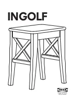
When  laying  concrete  slab,  ensure  there 
is  a  rebated  edge  25mm  deep  around  the 
perimeter.  This  will  help  water  egress  from 
the base of the shed.

For construction in non-cyclonic areas
Wind rating: N2 as per AS4055-2012

ABSCO INDUSTRIES

ASSEMBLY INSTRUCTION MANUAL

SHED MODEL: 23151GK 

21-11-2017  


CONCRETE SLAB

2360mm

1620mm

FRONT:   2.26m

SIDE:       1.52m

HEIGHT:  1.95m

We thank you for choosing an Australian made

shed. For further assistance please visit our detailed

instructional video library at

Http://www.abscosheds.com.au/watch-videos

At ABSCO Industries we are always looking to be

number ONE, so please let us know what you think

of our instructions. Feedback makes us better.

[email protected]

CONCRETE 

REBATED EDGE

BOTTOM CHANNEL

CONCRETE SLAB

75mm WIDE REBATE

100mm

WHEN LAYING YOUR CONCRETE

SLAB, ENSURE THERE IS A

REBATED EDGE 25mm DEEP

AROUND THE PERIMETER

THIS WILL HELP WATER EGRESS

FROM THE BASE OF THE SHED

Absco Industries

Premier Shed Model: 23151GK

PAGE 01

CONCRETE SLAB

4580mm

236

0mm

Summary of Contents for 45232WK

Page 1: ... ASSEMBLY INSTRUCTION MANUAL SHED MODEL 23151GK 21 11 2017 CONCRETE SLAB 2360mm 1620mm FRONT 2 26m SIDE 1 52m HEIGHT 1 95m We thank you for choosing an Australian made shed For further assistance please visit our detailed instructional video library at Http www abscosheds com au watch videos At ABSCO Industries we are always looking to be number ONE so please let us know what you think of our inst...

Page 2: ...elected your site you will need to lodge a site plan to your local council SITE PREPARATION The site for the shed must be level An uneven surface may result in misalignment of parts The shed shall be erected on top of a reinforced concrete slab and anchored down appropriately illustrated on FINAL CONSTRUCTION page If using a rebated slab ensure that all frame uprights are trimmed 25mm TOOLS REQUIR...

Page 3: ... COMPONENT DESCRIPTION PART No CHECK QTY QTY 2 2 12 1 STEEL SHEET 1915mm X 773mm 36L STEEL SHEET 1785mm X 711mm 34A 2 1 1 1 15A PEAK BRACE STEEL SHEET 1785mm X 711mm 35A STEEL SHEET 1725mm X 773mm A STEEL SHEET 1725mm X 773mm B 1 FITTINGS ACCESSORIES PACKET SEE PAGE 4 STEEL SHEET 1980mm X 773mm 42D STEEL SHEET 1170mm X 773mm 49A 1 97AL RIDGE BEAM L 1521mm 1 97C RIDGE BEAM L 1513mm ZARSP 1 RIDGE BE...

Page 4: ...NEL JOINER L 200mm 7 9 1 1 DOOR PADBOLT HASP 2 3 SELF TAPPING SCREWS PACKET CONTAINING 220 1 DOOR PADBOLT 3 16 COUNTERSUNK SCREWS NUTS 12 3 16 ROUND HEAD BOLTS NYLOCK NUTS 8 3 2 x 8mm BLIND POP RIVETS 12 PSTKDBL DOUBLE DOOR FITTINGS PACK PACK12P SCREW PACK 12 PACK12P SCREW PACK 12 1 PHILLIPS DRIVER BIT 3mm DRILL BIT DRILL FAST038 FAST007 FAST006 1 98A RIDGE CAP JOINER 10 16mm TEK SCREWS FAST014 1 ...

Page 5: ... X 773mm 36R STEEL SHEET 1785mm X 773mm 31A MID FRAME FITTINGS PACK SEE BELOW COMPONENT DESCRIPTION PART No CHECK CHECK QTY QTY 2 2 2 2 2 4 120 26 MID FRAME ACCESSORIES CHECK C1106 COMPONENT DESCRIPTION PART No C1704 CHANNEL L 1106mm 40 80 CHANNEL L 1704mm 40 80 KNEE PLATE APEX PLATE MULTI PURPOSE BRACKET DYNABOLT 16mm TEK SCREWS 45mm TEK SCREWS 1785mm X 773mm 30A STEEL SHEET 1 45232WCP J CHANNELP...

Page 6: ...CHECK COMPONENT DESCRIPTION PART No CHECK QTY QTY 55AL CHANNEL L 1496 5mm 1 1 1 55CL CHANNEL L 1496 5mm 55BL CHANNEL L 1496 5mm 2 81AL CHANNEL L 1496 5mm 2 60AL 2 CHANNEL L 1496 5mm 81CL CHANNEL L 1126 5mm 55AR CHANNEL L 1463 5mm 1 1 1 55CR CHANNEL L 1496 5mm 55BR CHANNEL L 1496 5mm 2 81AR CHANNEL L 1496 5mm 2 60AR 2 CHANNEL L 1496 5mm 81CR CHANNEL L 1126 5mm 1 81BL CHANNEL L 1496 5mm 1 81BR CHANN...

Page 7: ... 2 2 2 CHANNEL L 1513mm 81E 2 1 4 58B CHANNEL L 1725mm 1 58A CHANNEL WITH HINGES L 1725mm 2 60C CHANNEL L 1513mm 79A CHANNEL L 1568mm 58C CHANNEL L 773mm COMPONENT DESCRIPTION PART No CHECK COMPONENT DESCRIPTION PART No CHECK QTY QTY 2 1 4 1 4 89A JAMB L 1785mm 90A JAMB L 1568mm 91A JAMB L 1120mm 89C JAMB L 1725mm CHANNEL L 1143mm 83L CHANNEL L 1143mm 83R 86A LIP TRIM L 1170mm 45232WCP CHANNEL PAC...

Page 8: ...the channel along the sheets until each end is neatly flush If you need to remove channels from the panels slide it off from the side Channel locks the shed panel into position without the need for screws FASTENING SYMBOLS Secure channel to sheeting by SNAPTiTE fastening method Join components together with one screw at this location only as some channels have extra holes that are not required for...

Page 9: ...he end of the channel where the JOIN text is marked Push down one side of the CSJ until you hear a click Step 3 Join the second channel to the CSJ by positioning the JOIN of the channel at the centre of the CSJ on an angle Push the CSJ into the channel until you hear a click Finished Channel The joined channels should now look like the picture with the CSJ positioned equally inside of the joined c...

Page 10: ...u will need to redrill holes where CSJ joining channel covers them Join together 20 x channel sections using 10 x channel joiners Part CSJ 2 X 60AR 2993mm 117 8 2 x 81A 2 x 60A 1 x 55B 1 x 55C 55CL 55CR 55BR 55BL 60AR 60AL 81AL 81AR 2 X 81AR 2 X 81AL 2 X 60AL 1 X 55BR 1 X 55BL 1 X 55CR 1 X 55CL 2 x 81C 81CR 81CL 2 X 81CR 2 X 81CL 2253mm 88 7 1 x 55A 55AR 55AL 1 X 55AR 1 X 55AL 1 x 81B 81BL 81BR 1 ...

Page 11: ... a 50mm overlap of the ridge caps when the beams are in position Step 2 Use the ZARSP to connect at the centre of the two ridge beams Be sure it is pushed in fully Step 3 Turn over the ridge beam Measure 250mm from the middle along the centre of one ridge beam mark spacings of 50mm Fasten with a Tek screw at each marking Repeat to the other side of the ridge beam assembly TIP Predrilling each hole...

Page 12: ...ly Instruction Manual ABSCO WORKSHOP SHED MODEL 45232WK 4 48mW x 2 26mD x 2 00mH Model 45232WK 27 09 2018 1 30 12 PRE ASSEMBLY OF SPLICED RIDGE BEAM 1x 97AL 1x 97AR 1x 97A 2993mm Overall length ZARSP 225mm 16mm 97AL 97AR 16mm ...

Page 13: ...DGE BEAMS To make the total span we must now join the ridge beams 97A Using a hacksaw remove one protruding section of each ridge beam this will allow the sections to butt up neatly to each other Cut away these two only Finished Joined Ridge Beams Do not cut off the protruding section at each end of the full length ridge beam 97C 97A Section View 98A ...

Page 14: ...RKSHOP SHED MODEL 45232WK 4 48mW x 2 26mD x 2 00mH Model 45232WK 27 09 2018 1 30 14 OVERVIEW OF ROOF COMPONENTS OVERVIEW OF ROOF COMPONENTS 86A 86A 81A 81E 60A 60A 60C 60C 97C 97A 86A 86A 14A 14A 49A 49A 49A 49A 49A 49A 49A 49A 49A 49A 49A 49A 81A 98A 81E ...

Page 15: ...K 4 48mW x 2 26mD x 2 00mH Model 45232WK 27 09 2018 1 30 15 OVERVIEW OF WALL COMPONENTS OVERVIEW OF WALL COMPONENTS 22A 89A 91A 89A 91A 55C 81F 81B 83R 55B 53C 53C 83L 81F 81C MF 90A 15A 30A 31A 31A 31A 31A 30A 30A 31A 35A 34A A B 79A 83L 83R 15A 81C 36R 42D 36L 36L 42D 36R 55A ...

Page 16: ... Instruction Manual ABSCO WORKSHOP SHED MODEL 45232WK 4 48mW x 2 26mD x 2 00mH Model 45232WK 27 09 2018 1 30 16 END PANEL ASSEMBLY 1x required 1x required SNAPT TE i SNAPT TE i SNAPT TE i 55B 81B 30A 31A 31A 31A 53C 81F 31A 30A ...

Page 17: ...RGE ROOF PANEL ASSEMBLY 2 required One panel will have part 86A fitted to this end only One panel will have part 86A fitted to this end only Fit 81A to edge of sheet with pre punched holes SNAPT TE i SNAPT TE i 60A 87A 81A 87A 45A 45A 45A 45A D D When completed there will be two sections with 86A lip at one end only 86A 86A 49A 49A 49A 49A ...

Page 18: ... 30 18 SMALL ROOF PANEL ASSEMBLY 2 required One panel will have part 86A fitted to this end only One panel will have part 86A fitted to this end only Fit 81E to edge of sheet with pre punched holes D When completed there will be two sections with 86A lip at one end only 87A 60C 87A 45A 45A SNAPT TE i SNAPT TE i 81E 49A 49A 86A 86A ...

Page 19: ...sco Industries Assembly Instruction Manual ABSCO WORKSHOP SHED MODEL 45232WK 4 48mW x 2 26mD x 2 00mH Model 45232WK 27 09 2018 1 30 19 30A 31A 53C 81F SNAPT TE i SNAPT TE i FRONT PANEL ASSEMBLY 1 required ...

Page 20: ...mbly Instruction Manual ABSCO WORKSHOP SHED MODEL 45232WK 4 48mW x 2 26mD x 2 00mH Model 45232WK 27 09 2018 1 30 20 89A 89A 55A 90A 79A 55C SNAPT TE i SNAPT TE i SNAPT TE i SNAPT TE i 34A 35A FRONT PANEL ASSEMBLY 1 required ...

Page 21: ...0 21 58C 58C 58C 12A 58C 58A 58A A B 89C 58B A B SNAP T TE i SNAP T TE i SNAP T TE i SNAP T TE i Vertical door channels are installed in the opposite orientation compared to the horizontal door channels Four hole set for padbolt connection Short flange of channel Long flange of channel D D D D D D D D DOUBLE DOOR ASSEMBLY 1 required ...

Page 22: ...SEMBLY Nuts and bolts may be used instead of pop rivets by drilling out hinge holes using a 4mm drill bit Both are supplied The two holes required to connect the padbolt hasp for each door have not been pre punched to allow for proper alignment position each hasp centrally over the padbolt shaft and drill 3mm holes and secure with screws 91A 91A A B ...

Page 23: ...ction of this instruction set for further details and ensure that the assembled panels are not joined together with pre punched holes incorrectly positioned The overall length of each panel is the same as the ridge beam Trim the channels by 16 5mm to allow the sheets to be overlapped Overlap the panels and fasten as shown 16 5 16 5 It is not critical that the overall dimension is exact but try and...

Page 24: ...o Industries Assembly Instruction Manual ABSCO WORKSHOP SHED MODEL 45232WK 4 48mW x 2 26mD x 2 00mH Model 45232WK 27 09 2018 1 30 24 SIDE PANEL ASSEMBLY 2 required 36L 42D 36R 83R 81C 83L 15A INSIDE OF SHED ...

Page 25: ... bottom of the frame legs equal to the depth of the rebate TIP An easy way to make sure that the angle at the top of the portal frame is correct is to use the gable wall panel as a template to lay the sections out As the portal frame fits inside the walls the width of the frame will be 40mm less than the gable wall panel NOTE Refer to the section CENTRE PORTAL ASSEMBLY for photos of the process 17...

Page 26: ...L FRAME DETAILS STEP 1 Portal to panel connection see section PANEL CONSTRUCTION for further infomation Secure ridge plates to apex plates M10 Dynabolt Portal Self drilling tek screw Wall Roof panel STEP 2 STEP 3 STEP 4 x 19 x 30 x 8 x 8 x 6 2 x 0 8 18 4 45mm TEK SCREW WALL PANEL 2 PORTAL FRAME WALL PANEL 1 CENTRE LINE SLAB PORTAL FRAME WALL PANELS ...

Page 27: ...nual ABSCO WORKSHOP SHED MODEL 45232WK 4 48mW x 2 26mD x 2 00mH Model 45232WK 27 09 2018 1 30 27 CENTRE PORTAL ASSEMBLY SUPPORT PHOTOS STEP 1 Draw pattern on the concrete in accordance with the dimensions detailed in the assembly instructions ...

Page 28: ...es Assembly Instruction Manual ABSCO WORKSHOP SHED MODEL 45232WK 4 48mW x 2 26mD x 2 00mH Model 45232WK 27 09 2018 1 30 28 CENTRE PORTAL ASSEMBLY SUPPORT PHOTOS STEP 2 Understand where components are to be positioned ...

Page 29: ...ustries Assembly Instruction Manual ABSCO WORKSHOP SHED MODEL 45232WK 4 48mW x 2 26mD x 2 00mH Model 45232WK 27 09 2018 1 30 29 CENTRE PORTAL ASSEMBLY SUPPORT PHOTOS STEP 3 Join rafter to column with knee plate ...

Page 30: ...ustries Assembly Instruction Manual ABSCO WORKSHOP SHED MODEL 45232WK 4 48mW x 2 26mD x 2 00mH Model 45232WK 27 09 2018 1 30 30 CENTRE PORTAL ASSEMBLY SUPPORT PHOTOS STEP 4 Join both rafters using the apex plate ...

Page 31: ...bsco Industries Assembly Instruction Manual ABSCO WORKSHOP SHED MODEL 45232WK 4 48mW x 2 26mD x 2 00mH Model 45232WK 27 09 2018 1 30 31 CENTRE PORTAL ASSEMBLY SUPPORT PHOTOS STEP 5 Secure ridge plate RBP ...

Page 32: ... Industries Assembly Instruction Manual ABSCO WORKSHOP SHED MODEL 45232WK 4 48mW x 2 26mD x 2 00mH Model 45232WK 27 09 2018 1 30 32 CENTRE PORTAL ASSEMBLY SUPPORT PHOTOS STEP 6 Secure multi purpose brackets ...

Page 33: ...stries Assembly Instruction Manual ABSCO WORKSHOP SHED MODEL 45232WK 4 48mW x 2 26mD x 2 00mH Model 45232WK 27 09 2018 1 30 33 CENTRE PORTAL ASSEMBLY SUPPORT PHOTOS STEP 7 Turn frame over and repeat steps 4 and 5 ...

Page 34: ... DETAILS Secure multipurpose brackets to uprights using self drilling screws Move frames into postion mark and drill holes in slab using 10mm masonry drill bit Secure frames to slab with M10 dynabolts Concrete slab 4580mm x 2360mm Centreline of frame uprights FIG 8A Multi purpose brackets 80mm long Centre frame upright 1550 3030 4580 2360 SLAB EDGE ...

Page 35: ...h panel are pre punched for attaching roof sheeting The base channels are not Side wall channels fit into the notched rear wall channels Use 45mm self drilling screws to secure walls to centre frame With a concrete slab drill a 10mm hole instead of using the supplied hasp Pre punched channel to match ridge beam holes D D D D D D D D D D D D SHEETING PRE PUNCHED THIS END TO FOR CONNECTION TO FRONT ...

Page 36: ...ee A below STEP 2 Move the other roof panel into position and secure peak brace to ridge beam and roof panel with one screw at each end see B below STEP 3 Secure both roof panels to the walls with one screw in each corner first followed by two screws adjacent to the portal frame as shown STEP 4 Secure roof panels to the top chords of the portal frame using 45mm self drilling tek screws WARNING Do ...

Page 37: ...30 Ø Holes M10 Dynabolt Denotes hot dip galvanised finish Wall Sheet Slab 15 15 STEP 1 Secure the roof panels to the wall panels as shown STEP 2 Secure the roof panels to the internal frames with self drilling tek screws STEP 3 Secure the portal frames to the ridge beam as detailed on the previous page STEP 4 Bend the top and bottom flanges as shown then hook the bottom flanges under the top chann...

Page 38: ...e installation contractor Scaling of drawings shall not be undertaken 7 G Prior to commencing works on site the contractor shall verify the position of all services in the area to ensure that the construction does not interfere with any of those services 8 G During installation on site the shed structures shall be maintained in a stable condition with no part becoming overstressed or permanently d...

Page 39: ...5x45x3EA x 34mm long and 47x47x1 9EA x 80 long shall be minimum Grade 450 4 S All portal frame knee and apex plates shall be minimum Grade 450 5 S All roof and wall sheeting shall be minimum base metal thickness of 0 3mm 6 S All portal frame members shall be minimum base metal thickness of 0 75mm 7 S All snaptite channels and jambs shall be minimum base metal thickness of 0 42mm 8 S All top hats s...

Page 40: ...alified structural engineer The design shall consider all relevant provisions of AS3600 and AS2870 3 F Between adjacent footings or excavations the contractor installing the slab foundation shall not exceed a rise of 1 in a run of 2 in line of slope 4 F Unless approved in writing by the slab foundation engineer the limits of excavations near existing footings shall be in accordance with that indic...

Page 41: ...eelbarrows garden tools etc Storage items that might be adversely affected by any of the above conditions may require additional protection such as being sealed or covered by plastic sheets and or stacked above the concrete floor on timber slats Waterproof sealants may be used to offer further protection where required around joins and screw fixings as can rubber door seals and other products whic...

Page 42: ... The benefits given by the warranty are in addition to your other rights and remedies under a law in relation to the goods or services to which the warranty relates The warranty applies to the exclusion of all other representations guarantees or warranties express or implied our goods come with guarantees that cannot be excluded under the Australian consumer law and is not transferable You are ent...

Reviews: