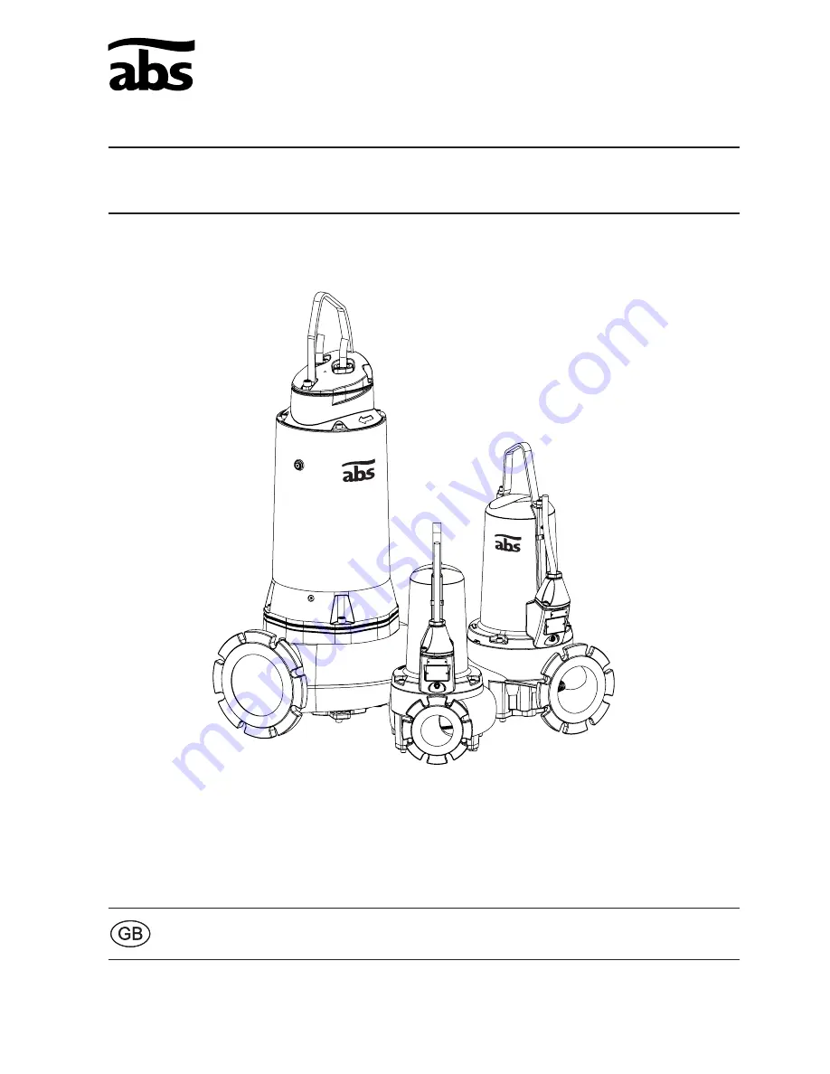
ABS submersible sewage pump XFP 80C - 201G
www.absgroup.com
08/201
1
Installation, Operating and Maintenance Instructions
Page 1: ...ABS submersible sewage pump XFP 80C 201G www absgroup com 08 2011 Installation Operating and Maintenance Instructions ...
Page 2: ...ng 12 8 2 Checking direction of rotation 12 8 3 Changing direction of rotation 13 9 Maintenance 13 9 1 General maintenance instructions 13 9 2 Maintenance of Lifting Stations in accordance with EN 12056 13 9 3 Lubricant changing PE1 PE2 14 9 4 Lubricant changing PE3 version without cooling jacket 15 9 5 Coolant changing PE3 version with cooling jacket 16 9 6 Oil and glycol quantities litres 17 9 7...
Page 3: ...vironmentally friendly solution The pumps are also suitable for horizontal or vertical dry installation except XFP 80E CB1 PE125 2 and XFP 81E VX PE125 2 60 Hz The regulations of DIN 1986 as well as local regulations should be observed when installing the pumps ATTENTION The maximum allowable temperature of the medium pumped is 40 C 1 1 Explosion proof approvals Explosion proof as standard in acco...
Page 4: ...ers and general queries Always state the pump type item no and serial no in all communications Standard nameplate Ex nameplate Legend Typ Pump type Nr Item No Sn Serial No xx xxxx Production date Week Year UN Rated voltage V IN Rated current A Ph Number of phases Hz Frequency Hz P1 Rated input power kW P2 Rated output power kW 1 min Speed r min Cos ij Power factor pf NEMA NEMA code Qmax Max Flow m3...
Page 5: ...ug 1 Pressure release screw 2 10 pole terminal block 3 Moisture sensor DI 4 Seal chamber 5 Seal chamber drain plug pressure test point 6 Venting plug 7 Stainless steel lifting hoop 8 Upper bearing single row 9 Motor with thermal sensors 10 Stainless steel shaft 11 Motor chamber 12 Lower bearing double row 7 Stainless steel lifting hoop 8 Upper bearing single row 9 Motor with thermal sensors 10 Sta...
Page 6: ...ring double row 10 Seal holding plate 11 Mechanical seals 12 Venting plug 13 Terminal block 14 Pressure test point 15 Upper bearing housing 16 Motor with thermal sensors 17 Stainless steel shaft 18 Moisture sensor DI 10 Seal holding plate 11 Mechanical seals 12 Venting plug 13 Terminal block 14 Pressure test point 15 Upper bearing housing 16 Motor with thermal sensors 17 Stainless steel shaft 18 M...
Page 7: ...ller is rotated by hand If the pump is being taken out of service the oil should be changed before storage After storage the pump should be inspected for damage the oil level should be checked and the impeller checked to ensure it rotates freely 5 2 1 Moisture protection of motor connection cable The motor connection cables are protected against the ingress of moisture along the cable by having th...
Page 8: ...transportable version arrange the cable run so that the cables will not be kinked or nipped Connect the discharge pipe and cable see section Electrical Connection Place the pump on a firm surface which will prevent it from overturning or burrowing down The pump can also be bolted down to the base or suspended slightly by the lifting handle Hoses pipes and valves must be sized to suit the pump perfo...
Page 9: ...turn valve 5 Power cable from motor to control panel 6 Pump 7 Collection sump 8 Inflow line 9 Ball type float switch 10 Gate valve ATTENTION PE3 pumps must not be dry installed without a cooling jacket Under continuous running conditions the pump motor housing may become hot To avoid burn injury allow to cool down before handling 1 2 3 4 5 6 8 7 9 10 1 2 3 4 5 6 8 7 9 10 1 2 3 4 5 6 8 7 9 10 1 2 3 4...
Page 10: ...low blow fuse corresponding to the rated power of the pump The incoming power supply as well as the connection of the pump itself to the terminals on the control panel must comply with the circuit diagram of the control panel as well as the motor connection diagrams and must be carried out by a qualified person All relevant safety regulations as well as general good technical practice must be compl...
Page 11: ...60 4 185 4 D05 D08 D20 220 4 D08 D05 D20 150 2 185 2 D05 D08 D20 250 2 D08 D05 D20 D01 400 V 3 DOL D05 400 V 3 Yǻ D14 230 V 3 DOL D20 230 V 3 Yǻ D07 500 V 3 DOL D08 500 V 3 Yǻ 60 Hz 1 2 3 4 5 20 6 22 4 28 4 35 4 D63 D68 D79 D80 D66 D62 D77 D85 45 2 D63 D79 D80 D64 D81 D66 D62 D77 D85 D86 18 4W 28 4W 20 6W W60 W62 35 6 45 4 56 4 75 4 90 4 105 4 80 2 125 2 D63 D79 D80 D64 D81 D66 D62 D77 D85 D86 120...
Page 12: ...either submerged or dry installed 8 2 Checking direction of rotation When three phase units are being commissioned for the first time and also when used on a new site the direction of rotation must be carefully checked by a qualified person When checking the direction of rotation the pump should be secured in such a manner that no danger to personnel is caused by the rotating impeller or by the resu...
Page 13: ...on occur do not improvise but ask your ABS Customer Service Department for assistance This applies particularly if the pump is continually switched off by the current overload in the control panel by the thermal sensors of the thermo control system or by the seal monitoring system DI Regular inspection and care is recommended to ensure a long service life Service intervals vary for XFP pumps depen...
Page 14: ...e any pressure that may have built up and re tighten Before doing so place a cloth over the plug screw to contain any possible spray of oil as the pump de pressurises Place the pump in a horizontal position sitting on its discharge flange with the motor housing supported from underneath To prevent the pump from toppling over ensure it is supported to lie flat on its discharge flange Position an adequ...
Page 15: ...ned Otherwise the pump may be damaged 9 4 1 Instructions on how to drain and fill the seal chamber Loosen the drain plug screw a enough to release any pressure that may have built up and re tighten Before doing so place a cloth over the plug screw to contain any possible spray of glycol as the pump de pressurises Secure a hoist to the lifting hoop Lay the pump on its side and rotate until the drai...
Page 16: ...to release any pressure that may have built up and re tighten Before doing so place a cloth over the plug screw to contain any possible spray of glycol as the pump de pressurises Secure a hoist to the lifting hoop Tilt the pump to 45 with the drain plug underneath Note because there is insufficient space to place a waste container underneath the drain plug by the completion of step 5 the waste must...
Page 17: ...E22 4 PE28 4 PE35 4 PE18 4W PE28 4W PE20 6 PE20 6W 0 43 PE 2 PE55 2 PE70 2 PE110 2 PE40 4 PE49 4 PE60 4 PE90 4 PE30 6 PE80 2 PE125 2 PE45 4 PE56 4 PE75 4 PE90 4 PE105 4 PE35 6 0 68 PE3 PE150 2 PE185 2 PE250 2 PE110 4 PE140 4 PE160 4 PE185 4 PE90 6 PE110 6 PE140 6 PE185 2 PE200 2 PE300 2 PE130 4 PE150 4 PE185 4 PE210 4 PE90 6 PE110 6 PE130 6 PE160 6 PE120 8 8 0 16 5 PE220 4 PE250 4 PE200 6 18 0 Vol...
Page 18: ...tion if due to corrosion the bottom plate does not release freely from the volute DO NOT force it free by tightening the adjusting grub screws d against the fixing lugs on the volute as this could damage the lugs on the bottom plate beyond repair In that case first remove the volute from the motor housing by releasing the three securing screws f and then remove the bottom plate by tapping it free fr...
Page 19: ...nsportable applications then in order to avoid deposits of dirt and encrustation it should be cleaned after each usage by pumping clear water In the case of fixed installation we recommend that the functioning of the automatic level control system be checked regularly By switching the selection switch switch setting HAND the sump will be emptied If deposits of dirt are visible on the floats then the...
Page 20: ...ontrol panel Check for impeller blockage If none of above a service inspection is required 1 Low head or flow Wrong direction of rotation Change rotation by interchanging two phases of the power supply cable Gap too wide between impeller and bottom plate Reduce gap see page 13 Gate valve partially open Open valve fully Excessive noise or vibration Defective bearing Replace bearing 1 Clogged impelle...
Page 21: ...sole responsibility that the products ABS submersible sewage pump XFP 80C 201G To which this declaration relates are in conformity with the following standards or other normative documents As defined by Machinery Directive 2006 42 EC EMC Directive 2004 108 EC Low Voltage Directive 2006 95 EC ATEX 94 9 EC Construction Products 89 106 EC II 2G k Ex d IIB T4 DIN EN 12050 1 EN 60335 EN 60079 0 2006 EN ...
Page 22: ...SERVICE LOG Pump Type Serial No Date Hours of Operation Comments Sign ...
Page 23: ...SERVICE LOG Date Hours of Operation Comments Sign ...
Page 24: ...Cardo Production Wexford Ltd Clonard Road Wexford Ireland Tel 353 53 91 63 200 Fax 353 53 91 42335 www absgroup com ...