


20. Electrical characteristics
MC97F6108A User’s manual
230
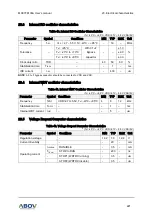
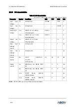
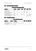
20.17
Data retention voltage in STOP mode
Table 54. Data Retention Voltage in STOP Mode
(T
A
=-40°C ~ +85°C, VDD=2.7V ~ 5.5V)
Parameter
Symbol
Conditions
MIN
TYP
MAX Unit
Data retention supply voltage V
DDDR
–
2.7
–
5.5
V
Data retention supply current I
DDDR
VDDR=
2.7V,
(T
A
=
25
°
C),
STOP mode
–
–
1
uA
Idle Mode
(Watchdog Timer Active)
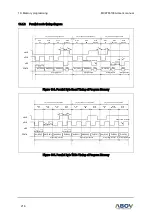
V
DD
INT Request
Execution of
STOP Instruction
~ ~
Data Retention
~ ~
Stop Mode
Normal
Operating Mode
0.8V
DD
t
WAIT
V
DDDR
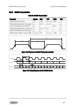
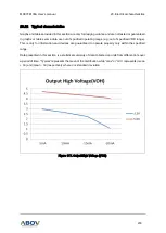
NOTE:
tWAIT is the same as (the selected bit overflow of BIT) X 1/(BIT Clock)
Figure 113. STOP Mode Release Timing when Initiated by an Interrupt
VDD
RESETB
Execution of
STOP Instruction
~ ~
Data Retention
~ ~
Stop Mode
Oscillation
Stabillization Time
Normal
Operating Mode
TWAIT
RESET
Occurs
0.2 VDD
V
DDDR
0.8 VDD
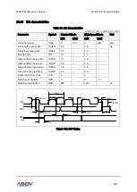
NOTE :
tWAIT is the same as (2048 X 32 X 2 X 1/fx) (8.192ms @ 16MHz)
Figure 114. STOP Mode Release Timing when Initiated by RESETB